Introduction
In oil refining, petrochemical processing, and heavy manufacturing, shell and tube heat exchangers are often the first component to fail — and the most expensive when they do. Unplanned downtime costs industrial facilities between $100,000 and $1,000,000 per hour, and reactive repairs cost up to 50% more than planned maintenance.
Corrosion, erosion, thermal cycling, vibration, and fouling all create predictable failure patterns — and most can be caught early. A reliability study of Lyondell Gulf Coast plants found that tube failures alone accounted for 31% of unplanned downtime, driving over $12 million in production losses.
That figure makes one thing clear: knowing what to look for matters.
This guide covers the most common shell and tube heat exchanger problems, their root causes, a step-by-step repair framework, and a clear fix-vs-replace decision guide.
TL;DR
- Most common failures: tube leaks, tube-to-tube sheet joint failures, fouling/scaling, and shell or tube sheet corrosion
- Repair options range from tube plugging to full re-tubing and protective coating application, depending on damage severity
- Consider replacement when repair costs approach 50% of replacement cost or structural damage is widespread
- Professional inspection before major repairs confirms the root cause and ensures ASME/API compliance
What Is a Shell & Tube Heat Exchanger?
A shell and tube heat exchanger is an industrial device that transfers heat between two fluids — one flowing through a bundle of tubes, the other circulating around the tubes inside an outer shell — without the fluids mixing.
Key components include:
- Shell: Outer cylindrical vessel that houses and protects the tube bundle
- Tube bundle: Parallel tubes carrying one fluid stream through the exchanger
- Tube sheets: End plates securing the tubes and keeping both fluid streams isolated
- Baffles: Internal plates that route shell-side flow across the tubes for better heat transfer
- Headers: End chambers that distribute fluid to and from the tubes
Each component plays a role in heat transfer efficiency while absorbing thermal cycling, corrosive fluids, and mechanical vibration over time. Understanding how these parts wear and fail is the starting point for any effective repair strategy.
Common Shell & Tube Heat Exchanger Problems and Their Root Causes
Most failures trace back to a small set of recognizable patterns. Knowing the symptom, its root cause, and which component is affected determines whether you're looking at a targeted repair or a full tube bundle replacement.
Tube Leaks and Tube-to-Tube Sheet Joint Failures
Symptoms: Visible leaks, cross-contamination of fluids, pressure drop, or reduced heat transfer efficiency
Likely causes:
- Corrosion or erosion of tube ends from aggressive process fluids
- Vibration-induced fatigue from flow instability or improper baffle spacing
- Poor initial joint fabrication with inadequate expansion or incomplete weld fusion
- Thermal expansion causing joint relaxation over repeated heat cycles
Tube-to-tube sheet joints are the most vulnerable component, with failures frequently initiated by fatigue cracks starting from initial defects at welded joints.
Tube Fouling and Scaling
Symptoms: Gradual decline in thermal performance, increased pressure drop, higher energy consumption
Likely causes:
- Mineral scale deposits from hard water or process fluids
- Biological fouling in cooling water systems
- Process fluid residue accumulating on tube surfaces
- Chemical reactions creating deposits at high temperatures
Fouling creates severe thermal resistance that can reduce heat transfer efficiency by up to 50%. In one documented refinery preheat train, fouling led to a 23% drop in heat duty over a single year, costing upwards of $50,000 daily in excess fuel consumption.
Tube Sheet Corrosion and Cracking
Symptoms: Visible pitting or cracking on tube sheet face, ligament damage between tube holes, structural weakening visible during inspection
Likely causes:
- Electrolytic (galvanic) corrosion from dissimilar metals in contact
- Aggressive chemical exposure (polythionic acid, sulfur compounds, chlorides)
- Erosion from high-velocity fluid impingement at tube entrances
- Under-deposit corrosion beneath scale or sediment layers
Shell-Side Damage (Baffles, Shell Corrosion)
Signs to watch for: Flow bypass, vibration noise, abnormal temperature differentials, visible external shell deterioration
Likely causes:
- Corrosion on shell interior from process fluid chemistry
- Broken or deformed baffles from excessive flow velocity or vibration
- Failure to address fouling on the shell side, creating flow maldistribution
- Stress corrosion cracking in weld zones
What happens when these problems are left unaddressed:
- Reduced thermal efficiency driving up energy costs
- Fluid cross-contamination creating product quality issues
- Safety and compliance risks, especially in ASME pressure vessels
- Unplanned shutdowns that halt connected processes and compound downtime costs
Each of these failure modes has a corresponding repair strategy — the sections below match the problem to the right fix.
How to Repair a Shell & Tube Heat Exchanger (Step-by-Step)
Attempting repairs without proper diagnosis leads to repeat failures, unnecessary part replacement, and wasted downtime. The steps below ensure the right fix is applied to the right problem.
Step 1: Inspect and Diagnose the Problem
Conduct a visual inspection for visible corrosion, leaks, scale deposits, or physical damage to tubes and tube sheets. Note any performance deviations such as reduced heat duty, elevated pressure drop, or fluid contamination.
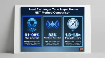
Use non-destructive testing (NDT) methods to identify hidden damage:
- Eddy Current Testing (ECT): Detects 91-98% of flaws in non-ferromagnetic tubes (stainless steel, titanium) at high speeds
- Ultrasonic IRIS: Achieves 83% detection for wall loss in carbon steel tubes
- Hydrostatic pressure testing: Verifies leak tightness at 1.3-1.5 times design pressure
Step 2: Identify the Repair Type Required
Map findings from inspection to one of the core repair categories:
- Joint re-expansion or re-welding
- Tube plugging
- Re-tubing (partial or full)
- Corrosion/coating repair
Confirm compliance requirements: because most heat exchanger repairs involve pressure-bearing components, work must be performed by qualified personnel and tested per ASME, API, or relevant engineering codes.
Step 3: Apply the Appropriate Repair
If Tube-to-Tube Sheet Joints Are Leaking (Joint Re-Expansion or Re-Welding)
For expanded joints that have relaxed: Carefully re-expand using torque-controlled equipment to maintain uniform wall reduction. Avoid over-expansion, which damages surrounding tube holes and the tube sheet.
For welded joints: Re-welding is possible as a short-term fix, but root causes are rarely eliminated by re-welding alone. The quality of repair welds is lower than original fabrication. Monitor closely after repair.
If Individual Tubes Are Failing (Tube Plugging)
Isolate the leaking tube by inserting a compatible plug (taper, expanding, or welded type based on operating conditions and TEMA standards). Plugged tubes are removed from service and no longer contribute to heat transfer.
Critical safety requirement: ASME PCC-2 Article 312 mandates that all plugged tubes must be pierced to provide venting and draining. This prevents pressure buildup that could cause a plug blowout, turning the plug into a dangerous projectile.
Plugging limitations:
- Friction-fit tapered plugs are strictly limited to services under 200 psi and 400°F
- Mechanical or welded plugs are required for higher pressures
- General industry practice allows plugging up to 10% of total tubes without significantly affecting performance
- Exceeding 10% reduces heat transfer area, increases pressure drop, and accelerates mechanical stress
Track total plug count relative to total tube count. Excessive plugging pushes the exchanger below acceptable performance thresholds.
If Widespread Tube Damage Exists (Re-Tubing)
Re-tubing involves removing some or all tubes and installing new ones while retaining the original shell and tube sheets. It is the preferred solution when plugging becomes excessive or tube life is near its end.
Common complications encountered during re-tubing:
- Heavy shell-side fouling requiring extensive cleaning
- Broken baffles needing replacement
- Deformed tubes difficult to extract
- Worn tube sheets requiring surface preparation
All must be addressed concurrently to avoid compromising the re-tube project. Re-tubing typically costs 40-60% of a new bundle and extends lifespan by 5-12 years.
If Tube Sheet or Shell Has Corrosion Damage (Surface Repair and Protective Coating)
For pitting, ligament cracking (cracking between adjacent tube holes), or surface erosion on tube sheets: rebuild damaged areas and apply a chemically resistant protective coating to restore the surface and prevent further corrosion attack.
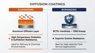
For long-term protection beyond standard epoxy coatings, advanced diffusion coatings — such as the boronizing and aluminizing processes offered by VaporKote — can be applied to heat exchanger components. These processes form an intermetallic surface layer directly on the base metal, delivering superior corrosion and wear resistance that outlasts applied surface treatments.
Both processes address different failure modes on heat exchanger components:
| Process | Mechanism | Best For |
|---|---|---|
| Aluminizing | Aluminum diffusion layer | High-temperature oxidation and sulfidation in refinery and chemical environments |
| Boronizing | RC75+ hardness (1500 Knoop) | Erosion resistance in high-velocity fluid service |
Because the coating diffuses into the base metal rather than sitting on top, it won't spall or delaminate under thermal cycling — a common failure point for epoxy and spray coatings in heat exchanger service.
Step 4: Test and Validate the Repair
Perform a hydrostatic or pneumatic pressure test after repair to confirm leak tightness before returning the exchanger to service. Monitor for recurrence during the initial operating period.
Document all repairs, plug locations, and test results for maintenance records and regulatory compliance. Note the condition of components for future inspection planning.
When to Fix vs. Replace Your Shell & Tube Heat Exchanger
The fix-or-replace decision comes down to three factors: extent of damage, remaining service life, and whether repair costs justify keeping the unit running. Here's how to read the situation.
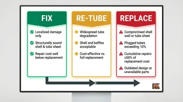
Fix when:
- Damage is localized (a small number of leaking tubes, a single joint failure, or surface corrosion on the tube sheet only)
- The shell and tube sheet remain structurally sound
- Repair cost is well below replacement cost
Re-tube when:
- Tube degradation is widespread but the shell, tube sheets, and baffles are still in acceptable condition
- Re-tubing is cost-effective compared to full replacement
- The repair restores the exchanger to near-original performance
Replace when:
- Corrosion or erosion has compromised shell wall thickness or tube sheet structurally beyond safe repair limits
- The number of plugged tubes exceeds TEMA-allowable limits (typically 10%)
- Cumulative repair costs approach or exceed the industry benchmark of 50% of replacement cost
- The original design no longer suits current process conditions — different temperatures, pressures, or fluid chemistry
- The unit is so old that spare parts are unavailable and repeated failures create unacceptable safety or compliance risk
On the wall loss question, ASME PCC-2 sets a clear threshold: when tube wall loss reaches 40% or more of nominal thickness, replacement should be on the table — not repair.
Preventive Measures to Extend Heat Exchanger Life
A well-maintained heat exchanger avoids the most disruptive and expensive failure scenarios. Shifting from reactive to condition-based maintenance delivers up to 545% ROI and reduces total maintenance costs by 25%.
Schedule regular inspections and cleaning:
- Establish inspection intervals based on fluid chemistry and service history
- Use NDT and hydrostatic testing during planned shutdowns
- Implement chemical or mechanical tube cleaning (hydrojet, brush, chemical flush) to prevent fouling buildup before it causes tube damage
- API 510 requires internal inspection intervals not exceeding one-half the remaining vessel life or 10 years, whichever is less
Apply protective surface treatments proactively:
For components in corrosive or erosive service, applying wear- and corrosion-resistant coatings during planned shutdowns can measurably reduce failure frequency. VaporKote's boronizing and aluminizing diffusion coatings protect against high-temperature corrosion, extend intervals between major repairs, and can be customized through on-site powder formulation for specific process environments. Their furnaces handle components up to 68 inches in diameter, covering most industrial exchanger sizes.
Control operating conditions and maintain documentation:
- Avoid operating outside design pressure and temperature limits
- Track vibration levels and address flow-induced vibration issues early
- Maintain detailed repair and inspection records to spot trends and plan proactive interventions before failures occur
- Use risk-based inspection (RBI) per API 580 to optimize maintenance scheduling
Frequently Asked Questions
Is it worth repairing a heat exchanger?
Repair is worth it when damage is localized, the shell and tube sheet are structurally sound, and repair costs are well below 50% of replacement cost. However, when cumulative repairs approach replacement cost or structural integrity is compromised, replacement becomes the better investment.
What can cause tube failure?
Common causes include corrosion, erosion from high-velocity fluids, vibration fatigue, thermal cycling stress, and fouling-induced under-deposit corrosion. Tube-to-tube sheet joint failures typically stem from poor initial fabrication or joint relaxation over time.
How is a leak in a heat exchanger tube detected?
The most reliable methods are hydrostatic pressure testing (at 1.3–1.5× design pressure), eddy current testing (ECT) for non-ferromagnetic tubes, and ultrasonic IRIS for carbon steel wall loss. Visual inspection during shutdown and monitoring for fluid cross-contamination also catch leaks in service.
What is tube plugging and when should it be used?
Tube plugging isolates individual failed tubes using mechanical plugs, removing them from service. Use it as a short-term or interim fix when only a few tubes are leaking, but limit plugging to 10% of total tubes — beyond that, reduced heat transfer capacity and increased pressure drop make re-tubing the better option.
How long does re-tubing a shell and tube heat exchanger take?
Duration depends on exchanger size, tube count, and whether work is done in a shop or on-site. Typical lead times run 2 to 5 weeks for bundle replacement, with the physical installation often completed in a matter of days.
How often should shell and tube heat exchangers be inspected?
API 510 sets internal inspection intervals at no more than half the remaining vessel life or 10 years, whichever is less. Annual inspections during planned shutdowns are standard, with more frequent monitoring required for corrosive or fouling-prone services.