Introduction
Engineers, maintenance teams, and procurement professionals routinely face design decisions on shell and tube heat exchangers that directly affect equipment longevity, operating costs, and plant uptime — and the wrong choices are expensive. Premature tube failures, unplanned re-tubing, and lost production are common consequences.
Shell and tube heat exchangers dominate oil refineries, chemical plants, power stations, and food processing facilities for good reason: these pressure vessels handle extreme temperatures, corrosive fluids, and operating pressures that would destroy most alternative designs.
The global shell and tube heat exchanger market is projected to grow from $6.9 billion in 2025 to $15.2 billion by 2035, driven by expanding chemical and petrochemical sectors — which means more facilities making these decisions under greater pressure than ever.
This guide covers shell and tube design fundamentals, component selection, material considerations, industrial applications, and proven strategies to protect tubes from the two biggest threats: fouling and corrosion.
TLDR
- Shell and tube heat exchangers transfer heat between two fluids using tube walls as the barrier — one fluid runs through the tubes, the other through the surrounding shell
- Preferred for high-pressure (1,500+ psi) and high-temperature duties where plate exchangers fail
- Key components—shell, tube bundle, baffles, headers—directly influence efficiency and maintenance access
- TEMA and ASME standards govern mechanical design; fluid allocation and material selection depend on pressure, corrosion, and fouling characteristics
- Diffusion coatings like boronizing significantly extend tube life in abrasive or corrosive service, cutting replacement frequency and unplanned downtime
What Is a Shell and Tube Heat Exchanger and How Does It Work
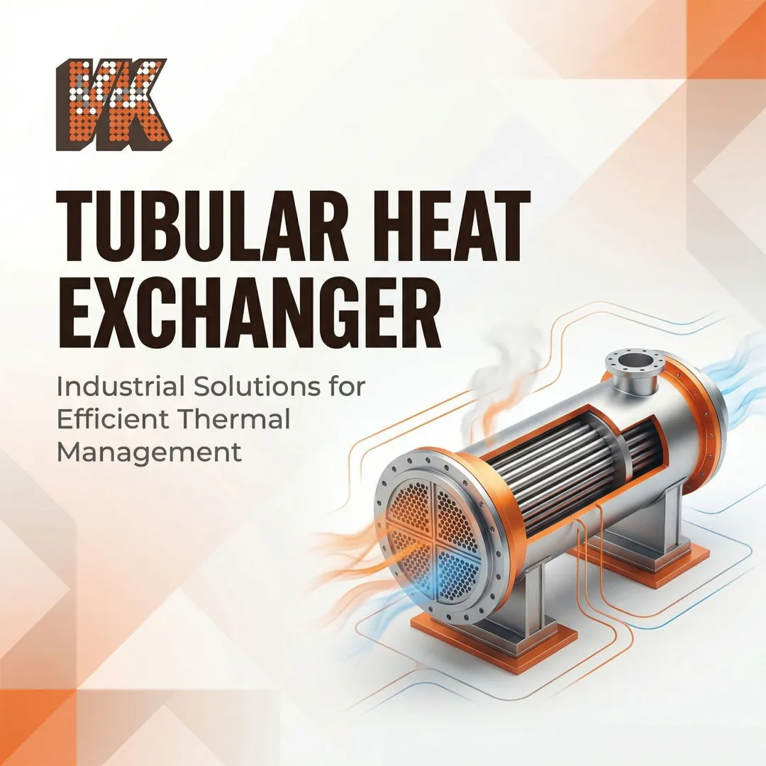
A shell and tube heat exchanger is a pressure vessel containing a bundle of tubes through which one fluid flows, while a second fluid flows around the outside of those tubes within the shell. Heat transfers across the tube walls without the fluids ever mixing, making this design ideal for applications requiring strict separation between process streams.
The system operates on two distinct fluid sides: the tube-side fluid flows inside the tubes, while the shell-side fluid flows around the outside of the tubes within the shell. Heat moves from the hotter fluid to the cooler one through conduction across the tube wall and convection on both sides.
Flow Arrangements and Multi-Pass Configurations
Three primary flow arrangements govern thermal performance:
- Counter-current flow — hot and cold fluids move in opposite directions, maintaining a larger temperature differential across the exchanger length and delivering the highest heat transfer efficiency
- Co-current (parallel) flow — both fluids travel in the same direction, producing lower thermal effectiveness but simpler piping in some layouts
- Multi-pass configurations — typically 2 or 4 passes, blending both patterns by reversing tube-side fluid direction multiple times within the exchanger
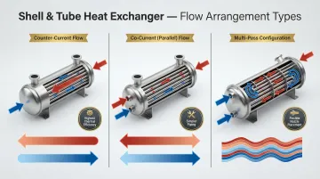
In single-pass designs, the tube-side fluid enters one end and exits the other. Multi-pass designs increase heat transfer surface contact time and allow inlet and outlet nozzles to sit on the same end — a practical advantage for piping layout and maintenance access.
The Critical Role of Turbulence
The same multi-pass and baffle configurations that shape flow patterns also drive turbulence — and turbulence is what makes heat transfer efficient. Industry guidelines specify Reynolds Numbers above 3,000 for shell-side fluids and above 10,000 for tube-side fluids to sustain fully turbulent conditions. Turbulence forces fluid against tube walls, increasing the heat transfer coefficient and improving overall exchanger performance.
Baffles on the shell side and tube inserts promote turbulence, but both raise pressure drop. Engineers target the turbulence threshold while keeping pressure drop within acceptable system limits — the defining balance in shell and tube exchanger design.
Key Components of a Shell and Tube Heat Exchanger
Shell
The outer cylindrical pressure vessel houses the tube bundle and carries the shell-side fluid. Shell diameters typically range from 150 mm to over 3,000 mm. Smaller shells use standard pipe sizes up to about 610 mm; larger units require rolled plate construction. Shell type selection (E, F, G, H, J, K, X) depends on pressure drop requirements and specific thermal duty.
Tube Bundle
The tube bundle is the core heat transfer element, consisting of:
- Tubes: Common diameters range from 12.7 mm to 50.8 mm, with 19.05 mm and 25.4 mm most prevalent
- Tube sheets: Thick metal plates at each end where tubes are rolled or welded, providing a seal between shell-side and tube-side fluids
- Tie rods and spacers: Maintain tube spacing and structural integrity
- Baffles: Direct shell-side flow and support tubes against vibration
Tubes can be plain, U-shaped, or longitudinally finned depending on application requirements.
Baffles
Baffles direct shell-side fluid flow across the tube bundle rather than straight through it, increasing turbulence and heat transfer. Baffle design falls into three main configurations:
- Single segmental (most common): One segment cut away, typically 20-35% of shell diameter
- Double segmental: Used when lower velocity and pressure drop are needed
- Disc-and-doughnut: Alternating full discs and doughnut-shaped baffles
Baffle pitch and cut percentage are the primary variables engineers adjust to balance heat transfer against allowable pressure drop.
Front and Rear Headers
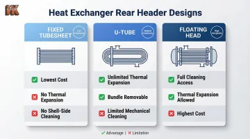
While baffles govern shell-side flow, the front and rear headers control how tube-side fluid enters, exits, and passes through the exchanger. The front (stationary) header is where tube-side fluid enters; the rear header is where it exits or returns for another pass. Rear header design drives key trade-offs between cost, thermal flexibility, and cleanability:
- Fixed tubesheet: Welded to shell—simplest and cheapest but no thermal expansion accommodation and no shell-side mechanical cleaning
- U-tube: Allows unlimited thermal expansion and bundle removal but limits mechanical tube-side cleaning
- Floating head: Allows both thermal expansion and full access for cleaning; suited for demanding high-temperature and high-pressure duties at higher cost
Nozzles and Impingement Protection
Beyond the headers, nozzle design is the final link in controlling fluid behavior at entry and exit points. Inlet and outlet nozzles on both shell and tube sides must be sized carefully to control fluid velocity and prevent erosion.
Impingement baffles or plates are often required at shell-side nozzle inlets to protect tubes from high-velocity fluid impact — a common cause of rapid erosion and premature tube failure.
Shell and Tube Heat Exchanger Design: Key Considerations
TEMA Designations
The Tubular Exchanger Manufacturers Association (TEMA) standardized a three-letter nomenclature:
- First letter: Front header type
- Second letter: Shell type
- Third letter: Rear header type
Common examples include BEM, AES, and CFU. TEMA classes define construction severity:
- Class R: Most severe refinery duties
- Class C: Commercial applications
- Class B: Chemical process service
Fixed tubesheets are cost-effective for clean services. U-tubes address thermal expansion concerns with clean tube-side fluids. Floating heads provide cleaning access on both sides for severe fouling duties.
Fluid Allocation: Tube-Side vs. Shell-Side
Deciding which fluid goes where is critical:
| Fluid Characteristic | Assignment | Rationale |
|---|---|---|
| High pressure | Tube side | Small-diameter tubes withstand more pressure than large shells, reducing wall thickness and cost |
| Corrosive | Tube side | Restricts expensive alloys to tubes and tubesheets; shell can be carbon steel |
| High fouling/solids | Tube side | Tube interiors are easier to clean mechanically than complex shell-side geometry |
| High viscosity | Shell side | Higher wall shear stress achievable on shell side improves heat transfer |
Misallocating fluids forces either oversized alloy construction or frequent unplanned cleaning shutdowns — both costly outcomes that proper allocation avoids at the design stage.
Tube Material Selection
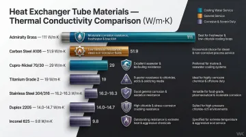
Material choice balances thermal conductivity, corrosion resistance, and mechanical strength:
| Material | Thermal Conductivity | Application |
|---|---|---|
| Carbon Steel (A106) | 51.9 W/m·K | General service; requires coatings in aggressive media |
| Stainless 304/316 | 16.2-16.3 W/m·K | Oxidizing acids; 316 better for chloride environments |
| Duplex 2205 | 14.0-14.7 W/m·K | Superior chloride stress corrosion cracking resistance |
| Admiralty Brass | 111 W/m·K | Cooling water; susceptible to ammonia |
| Cupro-Nickel 70/30 | 29 W/m·K | Seawater and biofouling resistance |
| Inconel 625 | 9.8 W/m·K | Severe acidic environments and pitting resistance |
| Titanium Grade 2 | 19 W/m·K | Immune to seawater corrosion |
Fluoropolymers (PFA, FEP) handle extreme chemical resistance but act as thermal insulators, requiring massive surface area increases.
For particularly harsh or abrasive environments, thermal diffusion coatings like boronizing extend base metal performance significantly. VaporKote's boronizing process achieves RC75+ equivalency surface hardness (1,500 Knoop) — surpassing tungsten carbide — protecting tubes from wear and chemical attack in petrochemical and refining service.
Baffle and Tube Layout Geometry
Tube layout patterns affect both performance and maintenance:
- Triangular (30°/60°): Higher tube density and heat transfer; difficult to clean mechanically
- Square (45°/90°): Lower density but allows mechanical cleaning access
Tube pitch (center-to-center distance) typically runs 1.25× tube OD minimum to ensure tubesheet structural integrity. Baffle cut percentage (typically 25% for double segmental, up to 45% for single segmental) is tuned to equalize crossflow and window velocities within allowable pressure drop limits.
Compliance with Design Codes
Mechanical design must comply with recognized pressure vessel codes:
- ASME BPVC Section VIII: Primary standard for pressure vessel construction (2025 Edition current)
- ASME Section II: Materials specifications
- ASME Section V: Non-destructive examination (NDE)
- API Standard 660: Additional requirements for petroleum and natural gas industries
TEMA standards work alongside ASME by providing dimensional and fabrication tolerances specific to heat exchangers. The TEMA 11th Edition (released July 2024) introduces updated mechanical design rules. Non-compliance with these codes can invalidate insurance coverage and disqualify equipment from regulated installations — making code conformance a commercial requirement, not just a technical one.
Industrial Applications of Shell and Tube Heat Exchangers
Oil and Gas / Petrochemical
Shell and tube heat exchangers dominate refineries and petrochemical plants due to their ability to handle high pressures, wide temperature ranges, corrosive hydrocarbons, and heavy fouling deposits. Specific duties include:
- Crude oil preheating in distillation units
- Fractionation column reboilers
- Overhead condensers
- Gas cooler/condenser applications
- Crude preheat train service, where organic fouling and coking demand periodic mechanical cleaning and protective coatings to maintain run lengths
Power Generation
Power plants rely on shell and tube exchangers for two critical duties:
- Surface condensers recover exhaust steam exiting turbines, converting it back to condensate under vacuum conditions
- Feedwater heaters raise boiler inlet water temperature, recovering energy that would otherwise be lost and improving overall cycle efficiency
Nuclear facilities take this further with large vertical U-tube steam generators — primary reactor coolant (radioactive) flows through thousands of tubes, boiling secondary water on the shell side to drive turbines without the two fluid circuits ever mixing.
Additional Industries
- Food and beverage: Pasteurization of milk, cooling of food-grade liquids, meeting 3-A sanitary standards and FDA food-contact requirements
- Pharmaceutical manufacturing: Sterile processing with clean-in-place (CIP) capabilities
- HVAC and chiller systems: Cooling hydraulic fluid, refrigerant-to-water heat exchange
- Marine propulsion: Engine cooling systems
- Aerospace testing: Thermal management in test facilities
Across all these industries, material selection — carbon steel, stainless, titanium, or coated alloys — is often the deciding factor in how long an exchanger lasts between maintenance intervals.
Advantages and Limitations Compared to Other Heat Exchangers
Key Advantages
- High-pressure capability: Handle 1,500+ psi (up to 3,000 psi per TEMA) versus ~450 psi limit for plate exchangers
- Easier maintenance: Tubes are accessible for cleaning, individual tubes can be plugged or replaced, and bundles are removable in floating head designs
- Lower fouling susceptibility: Lower shell-side fluid velocity reduces fouling rate compared to narrow plate channels
- Hazardous fluid containment: Welded pressure boundary preferred for lethal/toxic fluids over gasketed plate designs
- Double-walled tube option: Prevents cross-contamination in sensitive applications
Key Limitations
- Lower thermal efficiency: Heat transfer coefficient per unit surface area lower than plate exchangers
- Larger footprint: Requires significant floor space and tube-pull clearance for maintenance
- Fixed capacity: Cannot easily expand heat transfer capacity like adding plates to gasketed plate exchangers
Choosing Between Shell and Tube vs. Alternatives
These trade-offs directly shape the selection decision. Shell and tube is the right call when:
- Operating pressures exceed plate exchanger limits (>450 psi)
- Fluids are heavily fouling or contain particulates requiring mechanical cleaning
- One fluid is hazardous and containment integrity is paramount
- Extreme temperatures are involved (>200°C or <-50°C)
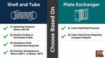
For lower-pressure, clean-fluid duties, plate exchangers deliver higher thermal efficiency in a smaller footprint — but that advantage disappears quickly once pressures climb or fluids turn aggressive.
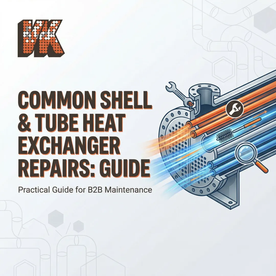
Protecting Heat Exchanger Tubes for Longer Service Life
Fouling and Corrosion as Primary Threats
The two biggest enemies of heat exchanger longevity are:
Fouling: Accumulation of scale, biological growth, corrosion products, or sediment on tube surfaces that reduces heat transfer efficiency and increases pressure drop. Fouling costs industrialized nations approximately 0.25% of GDP, with crude oil preheat train downtime alone exceeding $1 million per day in lost production.
Corrosion/Erosion: Chemical attack or abrasive wear that degrades tube wall integrity, leading to leaks, cross-contamination, and eventual replacement. Clogging and blockage account for 54% of common-cause failures in heat exchangers, followed by internal leakage at 41%.
The Role of Protective Diffusion Coatings
A proven strategy for combating corrosion and wear is applying advanced diffusion coatings—such as boronizing or aluminizing—to heat exchanger tube surfaces before service.
These coatings, applied through chemical vapor deposition, form an intermetallic compound that becomes an integral part of the tube surface rather than a separate layer. This provides dramatically enhanced hardness and corrosion resistance.
VaporKote's boronizing process achieves surface hardness of 1,500 Knoop (RC75+ equivalency)—harder than tungsten carbide cutting tools. In simulated downhole and geothermal environments with high-velocity slurries containing silica sand and corrosive brines, boronized carbon steel demonstrated negligible wall loss (<1%) while bare steel suffered severe wall loss under identical conditions.

In abrasive or chemically aggressive service, that performance difference translates directly into fewer re-tubing cycles, lower maintenance frequency, and measurable reductions in unplanned downtime.
For heat exchanger applications specifically, VaporKote offers aluminized heat exchanger tubing designed for protection against high-temperature corrosion. The aluminizing process creates a protective coating that prevents oxidation and surface degradation in extreme thermal conditions, allowing tubes to maintain wall integrity and heat transfer performance over longer service intervals.
Other Maintenance Best Practices
Implement a regular maintenance program including:
- Track pressure drop and heat transfer rates as early indicators of fouling buildup
- Clean tubes on a scheduled basis using hydro-blasting, brushing, or chemical methods depending on deposit type
- Inspect during outages with visual checks and dye-penetrant testing to catch leaks and corrosion early
- Verify sacrificial anode condition in systems where galvanic corrosion is a known risk
Frequently Asked Questions
What is a shell and tube heat exchanger?
It is the most common type of industrial heat exchanger, consisting of a cylindrical shell housing a bundle of tubes. One fluid flows inside the tubes while a second flows around them inside the shell, transferring heat across the tube walls without the fluids mixing.
When should you use a shell and tube heat exchanger?
Shell and tube exchangers are the right choice for high-pressure or high-temperature service that exceeds plate exchanger limits, fouling fluids that require mechanical cleaning access, hazardous fluid handling where containment integrity is critical, and large heat transfer duties in demanding industrial environments.
What are the advantages of shell and tube heat exchangers?
Key advantages include:
- Handle high-pressure, high-temperature service (1,500+ psi, extreme temperatures)
- Easier maintenance access via bundle removal, tube plugging, and re-tubing
- Lower fouling susceptibility compared to plate exchangers
- Broad material selection options for corrosive fluid service
Which is better, tube-side or shell-side, in a shell and tube heat exchanger?
The right choice depends on your application. Assign the higher-pressure, more corrosive, or fouling fluid to the tube side for better containment and cleaning access. Viscous or lower-pressure fluids typically go on the shell side. Safety, fouling tendency, pressure rating, and cost all factor into this decision.
What is a tube bundle in a shell and tube heat exchanger?
The tube bundle is the assembly of tubes, tube sheets, baffles, and tie rods that forms the core heat transfer element inside the shell. In floating head and U-tube designs, the bundle can be withdrawn from the shell for cleaning or replacement.
How do you detect a leaking tube in a shell and tube heat exchanger?
Pressurize the shell side and watch for fluid escaping from tube ends, or use dye penetrant testing and eddy current testing for precise location. Cross-contamination of the two fluid streams in service is also a reliable indicator of tube failure. Once identified, leaking tubes can be plugged, re-rolled, welded, or replaced during re-tubing.