Introduction
Tube bundle heat exchangers are the workhorses of petrochemical plants, oil refineries, power generation facilities, and manufacturing operations worldwide. When these critical assets begin to fail—through corrosion, fouling, or erosion—operators face a stark choice: source the right OEM-compatible replacement bundle and return to full capacity within days, or suffer weeks of downtime while waiting for a direct OEM unit.
Fouling alone costs the US refining sector $1.0 to $1.2 billion annually in lost energy and throughput. Add pitting corrosion, compatibility headaches when specifying replacements, and the hidden cost of low-quality alternatives—unverified materials, dimensional mismatches, voided insurance—and the financial exposure multiplies fast.
The stakes go beyond dollars. The 2010 Tesoro Anacortes refinery rupture killed seven workers due to undetected material degradation, a stark reminder of what cutting corners on heat exchanger integrity can cost.
With those stakes in mind, this guide covers:
- How tube bundles work and the three main configurations (fixed tubesheet, U-tube, floating head)
- Material selection for corrosive and high-temperature service
- Primary failure mechanisms and how to recognize them
- What OEM compatibility actually means in practice
- How advanced diffusion coatings extend service life in demanding applications
TLDR
- Tube bundles are the removable core of shell-and-tube heat exchangers—tubes, tubesheets, baffles, and tie rods—replaced independently of the shell
- Bundle type determines thermal flexibility: fixed tubesheets suit stable temperatures, U-tubes handle expansion, and floating heads offer the most flexibility at ~25% cost premium
- OEM-compatible bundles match original specs and typically deliver 30–50% cost savings over direct OEM purchase when properly certified
- Boronizing and aluminizing create 1500 Knoop (RC75+) intermetallic surfaces that outperform untreated metals in erosion and corrosion resistance
What Is a Tube Bundle Heat Exchanger and How Does It Work?
A tube bundle heat exchanger is a shell-and-tube device where two fluids at different temperatures exchange thermal energy through tube walls without mixing. One fluid flows inside the tubes (tube-side), while the other flows across the outside of the tubes within the shell (shell-side). This configuration allows precise control over heat transfer rates while maintaining complete separation between process streams.
The four major components are:
- Front header (stationary head): Directs tube-side fluid into the tube bundle; may include a removable channel cover for tube interior access
- Rear header: Returns tube-side fluid to the front header (in multi-pass designs) or directs it out of the exchanger
- Tube bundle: The removable core consisting of tubes, tubesheets (which hold tube ends), transverse baffles (which direct shell-side flow), and tie rods (which secure baffles in position)
- Outer shell: Contains the tube bundle and shell-side fluid under pressure, with nozzles for fluid inlet/outlet
Baffles play a critical role beyond structural support. By directing shell-side fluid across the tube bundle in a serpentine path, baffles increase turbulence and heat transfer efficiency. Because baffles attach to the bundle rather than the shell, the entire bundle can be removed as a single unit for maintenance or replacement.
What drives heat transfer rate:
The overall heat transfer coefficient (U) depends on several variables:
- Total tube surface area and wall thickness
- Temperature differential between fluids
- Thermal conductivity of the tube material
- Fluid flow rate and physical properties
Any degradation reduces exchanger efficiency. Fouling deposits, scaling, corrosion, and tube wall thinning all increase fouling resistance, which drives the overall heat transfer coefficient down (Kern, Process Heat Transfer). Operators then burn more fuel to hold process temperatures or accept reduced throughput.
Tube bundles are designed to be the replaceable "working core" of the heat exchanger. Replacing a degraded bundle is far more economical than replacing the entire unit, which is the foundation of the OEM-compatible replacement market.
Types of Tube Bundles: Fixed Tubesheet, U-Tube, and Floating Head
The Tubular Exchanger Manufacturers Association (TEMA) recognizes three primary tube bundle configurations. Configuration selection affects cleanability, thermal expansion tolerance, and total cost of ownership.
| Configuration | Thermal Expansion Handling | Cleanability | Relative Cost |
|---|---|---|---|
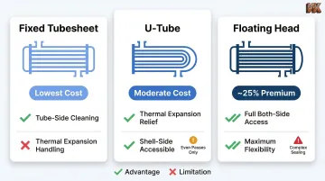
| Fixed Tubesheet | Poor (requires expansion joint if ΔT > 200°F) | Tube-side only | Lowest |
| U-Tube | Excellent (tubes expand independently) | Shell-side accessible; tube-side difficult | Moderate |
| Floating Head | Excellent (entire bundle floats) | Full access both sides | Highest (~25% premium) |
Straight Tube (Fixed Tubesheet) Bundle
In a fixed tubesheet bundle, tubes run straight from one end to the other with tubesheets welded directly to both ends of the shell. This is the simplest and most economical configuration. Tube interiors are accessible for mechanical cleaning, but shell-side cleaning requires chemical methods since the bundle cannot be removed.
Large temperature differentials between shell and tube fluids (generally above 200°F) cause differential thermal expansion, creating severe stress at the tubesheet-to-shell weld joint. This often requires adding a costly shell-side expansion bellows, a potential reliability concern for demanding service conditions.
U-Tube Bundle
Where fixed tubesheet designs struggle with thermal expansion, U-tube bundles offer a direct solution. Tubes are bent into a U-shape with both inlet and outlet on the same end of the shell, allowing the entire bundle to be withdrawn for shell-side cleaning and providing unlimited thermal expansion relief — making this configuration well-suited for high-temperature applications.
Mechanical cleaning of U-bend interiors is difficult, so this design is best reserved for clean tube-side fluids. U-tube bundles are also strictly limited to an even number of tube passes — odd-pass configurations are not possible. This constraint can limit flow velocity optimization and prevent pure countercurrent flow unless an F-Type shell is used.
Floating Head Bundle
Floating head designs (most commonly the S-type split ring rear header) allow one tubesheet to move freely inside the shell. This accommodates thermal expansion, enables full bundle removal for cleaning on both sides, and makes this configuration the preferred choice for high-temperature, high-pressure, or fouling-heavy duties.
The cost premium is significant: floating head exchangers typically cost approximately 25% more than equivalent fixed tubesheet designs in carbon steel. Furthermore, internal gaskets (like in the S-Type split ring) introduce hidden leak paths that require careful maintenance.
Tube Bundle Materials: Matching Alloy to Application
Choosing the right tube material for an OEM-compatible replacement starts with three variables: fluid chemistry, operating temperature and pressure, and corrosion or erosion risk. Getting this wrong on a drop-in replacement can accelerate failure faster than the original degraded component.
Common tube materials:
- Carbon steel (ASTM A179): Clean, non-corrosive services; tubular heat exchangers and condensers
- Admiralty brass (ASTM B111 C44300): Cooling water and condenser applications; excellent thermal conductivity
- Cupro-nickel 90/10 or 70/30 (ASTM B466): Seawater service, marine systems, desalination; high biofouling resistance
- Austenitic stainless steel (304/316, ASTM A213/A249): Corrosive chemical processing; high-temperature boiler and superheater tubes
- Duplex stainless steel: Chloride-containing environments requiring higher strength than austenitic grades
- High-performance alloys (Inconel, Incoloy, Monel): Extreme temperature, pressure, or corrosion environments
Upgrading materials significantly impacts costs: moving from carbon steel to 316L stainless steel adds 40–60% to base costs, while exotic alloys like Inconel 625 carry a +200% premium.
Galvanic Corrosion Risks
Material compatibility between tube bundle and shell is non-negotiable for galvanic corrosion prevention. When dissimilar metals contact each other in a conductive environment, the less noble metal (anode) corrodes at an accelerated rate — sometimes catastrophically fast.
A common failure mode: installing noble titanium or Inconel tubes into a less noble copper-alloy or carbon steel tubesheet. The smaller anodic tubesheet corrodes at a highly accelerated rate, leading to premature joint failure and cross-contamination of process fluids.
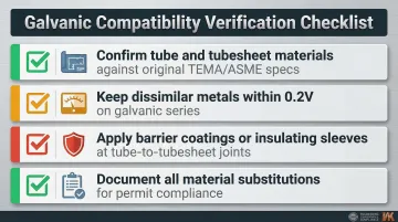
When specifying OEM-compatible replacements, verify galvanic compatibility with this checklist:
- Confirm tube and tubesheet materials against original TEMA/ASME specs
- Check galvanic series position — keep dissimilar metals within 0.2V of each other where possible
- Apply barrier coatings or insulating sleeves at tube-to-tubesheet joints when upgrading to a more noble alloy
- Document all material substitutions for permit compliance review
Dimensional Standards and Code Compliance
In the petrochemical and process industries, tube outside diameters are standardized to 0.75 inches (19.05 mm) and 1.0 inches (25.4 mm). Tube wall thickness and diameter must conform to ASME Boiler & Pressure Vessel Code (BPVC) Section VIII, specifically Part UHX. Deviating from OEM specifications affects both performance and compliance with operating permits.
How Tube Bundles Fail: Corrosion, Erosion, and Fouling
Three Primary Failure Mechanisms
1. Corrosion: General and pitting corrosion from aggressive process fluids or improper material selection. Chlorides, sulfides, and acidic condensates are common culprits. Galvanic corrosion accelerates failure when dissimilar metals are improperly paired.
2. Erosion: High-velocity fluid impingement wearing tube walls, especially at inlet nozzles, baffle contact points, and U-bend apexes. Particulate-laden fluids or two-phase flow dramatically accelerate erosion rates.
3. Fouling: Scale, biological growth, or process deposits building up on tube surfaces. Fouling adds thermal resistance that destroys the overall heat transfer coefficient, forcing furnaces to burn more fuel to achieve required temperatures. Studies estimate fouling costs roughly 0.25% of GDP in industrialized countries, with additional fuel burned contributing 1% to 2.5% of global CO2 emissions.
Recognizing Bundle Degradation
Operational symptoms:
- Rising shell-side or tube-side pressure drop
- Declining heat transfer coefficient — seen as rising cold-side outlet temps or falling hot-side outlet temps
- Tube leaks between shell and tube fluids (detected by fluid contamination or pressure loss)
- Visible pitting, thinning, or cracking during inspection
Inspection methods:
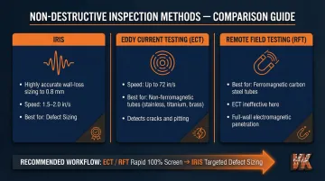
- IRIS (Internal Rotary Inspection System): Ultrasonic method providing highly accurate wall-loss sizing (detects defects down to 0.8 mm) but slow (1.5–2.0 in/s) and requires tubes flooded with water
- Eddy Current Testing (ECT): Fast (up to 72 in/s) and excellent for detecting cracks and pitting in non-ferromagnetic tubes (stainless, titanium, brass, cupro-nickel)
- Remote Field Testing (RFT): For ferromagnetic carbon steel tubes where conventional ECT is ineffective
Best practice involves using ECT or RFT for rapid 100% bundle screening, followed by IRIS to accurately size specific defects identified during screening.
Financial Consequences of Delayed Action
Ignoring early warning signs leads to unplanned shutdowns, contaminated process streams, and accelerated damage to adjacent components. The 2010 Tesoro Anacortes refinery rupture illustrates the worst-case outcome: High Temperature Hydrogen Attack (HTHA) in a carbon steel shell resulted in seven fatalities and a prolonged regulatory shutdown.
Proactive inspection schedules aligned with API 510 Risk-Based Inspection (RBI) methodologies prevent such failures by detecting degradation before containment is lost.
What OEM-Compatible Really Means for Tube Bundle Replacements
Definition and Dimensional Requirements
"OEM-compatible" means a replacement bundle cross-referenced to the original manufacturer's specifications—matching:
- Tube count, tube OD, and wall thickness
- Baffle spacing, baffle cut percentage, and baffle type
- Tube pitch (triangular or square) and tube layout pattern
- Tubesheet dimensions, thickness, and nozzle orientation
- Overall bundle length and tie rod configuration
This ensures a drop-in fit within the existing shell without modifications.
Cost Savings vs. OEM Direct Purchase
The primary advantage: OEM-compatible bundles from specialized fabricators typically offer 30% to 50% cost savings compared to OEM prices. However, actual savings fluctuate based on material selection, ASME certification requirements, and regional labor rates. The 30–50% range represents a best-case scenario for standard carbon-steel units.
Non-Negotiable Documentation
Before purchasing an OEM-compatible bundle, verify:
- TEMA class rating (R, C, or B) — R for rigorous petroleum/refining service, C for moderate commercial use, B for chemical process applications
- EN 10204 Type 3.1 MTRs confirming tube material grade, alloy chemistry, and full traceability
- ASME U-stamp compliance for all pressure-boundary components under ASME BPVC Section VIII
- Dimensional certificates verifying tolerances against the specified TEMA class
- Baffle configuration and nozzle orientation matching the original design for correct flow distribution
Upgrading Beyond Original Specs
"Compatible" does not mean "identical." Buyers can specify upgrades at replacement time—higher-grade tube alloys, enhanced baffle designs, or surface-treated components—to extend service life beyond the original bundle without modifying the shell.
Common upgrade strategies:
- Upgrading from carbon steel to 316L stainless steel for improved corrosion resistance
- Specifying duplex stainless steel for chloride-containing services
- Adding impingement plates at high-velocity inlet zones
- Applying diffusion coatings to tubesheets, baffles, and tube ends
The flip side of informed upgrades is uninformed substitution — which is where replacement projects go wrong.
Risks of Unverified Bundles
Non-certified or unverified bundles introduce serious risk:
- Dimensional mismatches: Incorrect tube pitch, baffle spacing, or overall length prevents proper installation or creates flow maldistribution
- Substandard material substitutions: Using lower-grade alloys than specified accelerates corrosion and premature failure
- Absence of proper documentation: Voids compliance with operating permits and insurance requirements
Operating non-certified equipment can lead to rejection during jurisdictional inspections, voided boiler and machinery insurance coverage, and potential safety violations. Require full documentation — MTRs, dimensional certificates, and code compliance statements — before accepting any bundle.
Extending Tube Bundle Service Life with Diffusion Coatings
Even correct alloy selection cannot always withstand extreme corrosion, high-temperature oxidation, or abrasive erosion in demanding process environments. Advanced surface treatments like diffusion coatings create an intermetallic compound layer on tube and component surfaces that outperforms untreated or conventionally coated metals.
How Diffusion Coatings Work
Unlike thermal spray coatings or electroplating—which deposit a surface layer that can spall or delaminate under thermal cycling—diffusion coatings form a metallurgical bond with the base material through high-temperature chemical vapor deposition (CVD). The coating element (boron or aluminum) diffuses into the base metal, creating an intermetallic phase that is integral to the substrate.
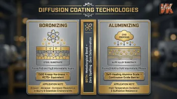
Boronizing: Diffuses boron into steel to form ultra-hard iron boride layers (FeB and Fe₂B). These layers provide exceptional resistance to synergistic erosion-abrasion-corrosion, particularly in harsh downhole or slurry environments. VaporKote's boronizing process achieves surface hardness of 1500 Knoop (RC75+ equivalency)—harder than tungsten carbide cutting tools.
Aluminizing: A CVD process that diffuses aluminum into Fe or Ni alloys to form intermetallic phases (e.g., β-NiAl or FeAl). These coatings drastically improve high-temperature oxidation and sulfidation resistance by forming a protective alumina scale that self-heals under oxidizing conditions.
Which Components Benefit Most
Diffusion coatings deliver the greatest value on tube bundle components most vulnerable to erosion and corrosion:
- Tubesheets: Particularly at tube-to-tubesheet joints where crevice corrosion initiates
- Baffles: At contact points with tubes where fretting wear occurs
- Impingement plates: At high-velocity inlet zones where erosion is most severe
- Tube ends: Where flow turbulence and velocity are highest
VaporKote serves customers in petrochemical refining, oil production, and heat exchanger manufacturing industries, providing aluminized heat exchanger tubing designed for optimal protection against high-temperature corrosion. The company's diffusion coating capabilities extend to large components up to 68 inches in diameter, accommodating industrial-scale tubesheets and baffles.
The Business Case for Coated Components
Fouling costs the US refining sector $1.0 to $1.2 billion annually, but erosion and corrosion failures trigger even more costly unplanned shutdowns. A single unplanned exchanger replacement in a critical service can cost $500,000 to $2 million when factoring in emergency procurement, expedited fabrication, lost production, and restart costs.
Treating vulnerable components with diffusion coatings upfront adds 15–25% to component cost but can extend service life by 3–5× compared to untreated equivalents. For a $200,000 replacement bundle, investing an additional $40,000 in diffusion coatings that extends service life from 5 years to 15 years eliminates two full replacement cycles and the downtime costs that come with each.
VaporKote adheres to ASTM, ASME, SAE, and API engineering codes, providing metallurgical analysis and certification of diffusion coatings to meet compliance requirements for operating permits.
Frequently Asked Questions
What is a heat exchanger tube bundle?
A tube bundle is the removable internal assembly of a shell-and-tube heat exchanger, consisting of tubes, tubesheets, baffles, and tie rods. One fluid flows inside the tubes while the second fluid passes across the outside within the shell, enabling heat transfer without fluid mixing.
What are the different types of tube bundles?
The three main types are fixed tubesheet (straight tube), U-tube, and floating head. Fixed tubesheet bundles are economical but vulnerable to thermal stress. U-tubes handle expansion but are limited to even tube passes. Floating head designs offer maximum cleanability and thermal expansion handling at approximately 25% cost premium.
What is the best tube for a heat exchanger?
The best tube material depends on process fluid chemistry, temperature, and pressure. Stainless steel and duplex alloys are common for corrosive services. Carbon steel suits lower-corrosion, high-pressure applications. High-alloy materials like Inconel are specified for extreme environments with high temperatures, aggressive chemicals, or combined corrosion-erosion conditions.
What is the 2/3 rule for heat exchangers?
The 2/3 rule states that a heat exchanger should be considered for replacement or retubing when more than one-third of its tubes have been plugged or failed. Beyond that threshold, pressure drop rises and thermal efficiency drops enough that continued operation costs more than retubing.
What is the 10/13 rule for heat exchangers?
The "10/13 rule" is a colloquial heuristic for setting design pressures relative to hydrotest pressures — since hydrotest is typically 1.3× MAWP, the ratio works out to roughly 10/13. It is often confused with baffle spacing, which TEMA 9th Edition codifies separately: minimum spacing is one-fifth of shell ID or 2 inches, whichever is greater.
Are heat exchangers worth the money?
Yes. Heat exchangers typically pay back their cost through energy recovery alone within 1–3 years in continuous process operations. Investing in OEM-compatible bundles with advanced materials or diffusion coatings extends service intervals and lowers total lifecycle cost compared to repeated early-failure replacements.