Introduction
Temperature sensors in oil & gas pipelines, petrochemical reactors, and power generation systems face a punishing environment — corrosive media, high-pressure flow, abrasive particles, and vibration that can destroy a bare sensor in months.
Pulling the line offline to swap out a failed sensor costs far more than the sensor itself. Unplanned process shutdowns in chemical facilities alone can run into the hundreds of thousands of dollars per incident.
The thermowell solves this directly. It's a closed-end metal fitting installed permanently in the pipe wall that shields the sensor from process conditions while keeping the sensor itself accessible from outside. The sensor goes in, the process stays sealed, and when the sensor fails, you pull it out and insert a replacement — no draining, no shutdown.
This guide breaks down thermowell design, materials, and selection — everything needed to specify the right one for the application.
Key Takeaways
- A thermowell is a closed-end metal tube that protects temperature sensors from corrosive, high-pressure, and high-velocity process conditions
- Heat transfers through the thermowell wall to the sensor tip — no direct fluid contact required
- Stem design and connection type are selected based on flow velocity, pressure, and maintenance requirements
- Material selection must match process chemistry and erosion potential; options range from 316 SS to Inconel to boronized steel
- Wake frequency compliance per ASME PTC 19.3 TW is mandatory for any significant flow velocity
What Is a Thermowell and How Does It Work
A thermowell is a cylindrical, closed-end metal fitting machined from bar stock or fabricated from tubing. It installs through the wall of a pipe or vessel with the closed end immersed in the process fluid and the open end accessible from outside. The temperature sensor — thermocouple, RTD, or bimetal thermometer — inserts into that open end.
The Heat Transfer Chain
Temperature measurement follows a direct path: process fluid → thermowell wall → sensor tip → sensor output signal, with each step introducing a slight delay. According to WIKA, this lag can range from seconds to minutes depending on installation. A mismatch between the sensor sheath and bore diameter makes it worse — one POWER Magazine steam study found bore mismatch alone increased the thermal time constant from roughly 19 seconds to 64 seconds, and improper sensor seating pushed it from 30 seconds to 300 seconds.
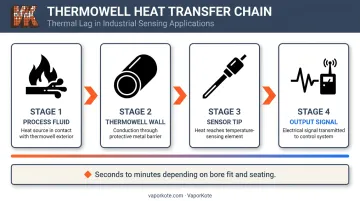
That response lag is the cost of protection — and in demanding process environments, it's a worthwhile exchange.
What the Thermowell Prevents
Direct sensor immersion in demanding process environments means exposure to:
- Corrosive acids, caustics, and chemical media
- High-pressure fluid that would breach unprotected sensor fittings
- High-velocity flow that induces vibration fatigue
- Abrasive particles that erode sensor sheaths rapidly
- Thermal cycling stress
The thermowell absorbs all of this. Because it remains permanently sealed in the process connection, a degraded sensor can be withdrawn and replaced from outside without isolating the line or halting production.
Governing Standard
ASME PTC 19.3 TW-2016 is the primary code for thermowell design and mechanical integrity. It covers:
- Nomenclature and shank configurations (straight, tapered, step)
- Natural frequency calculations
- Flow-induced stress equations
- Static and dynamic stress limits
Any thermowell installation in critical service should be designed and verified against this standard.
Key Components of a Thermowell
A thermowell has five distinct sections, and each one controls a different aspect of performance — from how the sensor reads temperature to how the assembly survives process pressure.
Stem (Shank)
The immersed portion bears all mechanical forces — process pressure, flow-induced vibration, and erosion. Stem geometry (straight, stepped, or tapered) determines structural strength, vibration resistance, and thermal response. Tapered stems, for instance, reduce wake frequency and lower the risk of resonance failure in high-velocity flow conditions.
Bore
The internal diameter that accepts the sensor. Standard sizes include 0.260" for 0.250" OD sensors and 0.385" for 0.375" OD sensors (per Pyromation and Omega specifications). Bore-to-sensor fit matters: gaps between the sensor sheath and bore wall create insulating air pockets that slow heat transfer and reduce measurement accuracy. Engineers often use spring-loaded sensors to maintain firm tip-to-bore contact and eliminate that gap.
Process Connection
The feature that attaches the thermowell to the pipe or vessel — threaded, flanged, or welded. This section forms the pressure boundary and determines how the thermowell is installed and eventually serviced. Flanged connections suit high-pressure classes and frequent removal; threaded connections work for moderate pressures where inline access is less critical.
Lagging Extension
The section above the process connection that passes through pipe insulation or cladding, keeping the sensor head accessible outside the insulated surface. Common applications include:
- HVAC systems with thick duct or pipe insulation
- Chilled water piping with vapor barrier jacketing
- High-temperature process lines with mineral wool cladding
Without the correct extension length, the sensor head ends up buried inside the insulation — making wiring, calibration, and replacement difficult.
Instrument Connection / Head
The top-end interface where the sensor's lead wires or transmitter housing connects. Exposed to ambient conditions, this section must accommodate the specific sensor type being used.
Types of Thermowells
Thermowell Stem Designs
The three stem profiles address different trade-offs between strength, response time, and vibration resistance:
| Stem Type | Profile | Strengths | Best For |
|---|---|---|---|
| Straight | Uniform OD from root to tip | Maximum erosion resistance, simplest construction | Low-velocity flow, maximum mechanical protection |
| Stepped | Large OD reducing to smaller OD near tip | Faster response than straight, good root stiffness | Steam systems, gas pipelines |
| Tapered | OD decreasing gradually root to tip | Best balance of vibration resistance, strength, response | High-velocity, high-pressure service (refineries, power plants) |
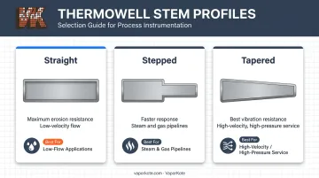
Tapered thermowells are the most widely specified for demanding service. The gradual reduction in cross-section improves natural frequency while maintaining root strength.
Stem profile determines how the thermowell handles flow forces. How it connects to the process line determines sealing integrity and how easily it can be removed for maintenance.
Thermowell Connection Types
- Threaded: Screws into a tapped coupling or nozzle. Most common, lowest cost, easiest to remove for inspection or replacement. Suited to smaller line sizes and lower pressure classes
- Flanged: Bolts to an existing flange or nozzle per ASME B16.5. Preferred for larger line sizes, higher pressure ratings, and applications requiring consistent alignment on repeated removal
- Weld-in / socket-weld: Permanently welded into the process connection, eliminating any threaded leak path. Best for high-temperature, high-pressure, or continuous service where long-term integrity outweighs maintenance access
Beyond connection type, some applications call for purpose-built designs that address specific failure modes.
Special Thermowell Designs
Scruton (helical strake) thermowells incorporate a helix on the outer stem surface that disrupts Karman vortex formation, suppressing vortex-induced vibration. WIKA's endurance testing in gasoil flow found a standard thermowell deflected 27 mm at 4.5 m/s, while the helical design deflected only 1.2 mm — roughly 95% less. Engineers specify these when standard designs fail the wake frequency check.
Sanitary thermowells use hygienic connections (tri-clamp, sanitary flange) and crevice-free finishes to prevent microbial growth. They meet FDA 21 CFR Part 117 requirements and 3-A Sanitary Standard 74-07 for food and dairy processing, pharmaceutical manufacturing, and biotech applications.
Thermowell Materials and Protective Coatings
Material choice is not just about corrosion resistance — it involves temperature limits, flow velocity, abrasive content, and compatibility with the pipe or vessel material.
Common Materials by Application
| Material | Characteristics | Typical Use |
|---|---|---|
| 316 Stainless Steel | Good corrosion resistance, cost-effective | General-purpose process service |
| Carbon Steel | Low corrosion resistance | Low-temperature, non-corrosive only |
| Inconel 625 | High strength, oxidation resistance to 982°C | Extreme temperatures, aggressive oxidizing environments |
| Monel 400 | Excellent marine and chemical resistance | Seawater, hydrofluoric acid service |
| Hastelloy C-276 | Resists sulfur compounds, chloride pitting | Sour gas, chloride-rich chemical environments |
Key Material Selection Factors
Engineers must evaluate:
- Process chemistry and pH — acids, caustics, chlorides, and sulfides each attack different alloys
- Operating temperature — higher temperatures accelerate corrosion and reduce alloy strength
- Fluid velocity and solids content — abrasive particles erode even stainless steel stems at high velocity
- Galvanic compatibility — thermowell material should be compatible with the mating pipe or vessel alloy
Protective Diffusion Coatings
When the base alloy alone won't hold up, surface diffusion coatings extend service life significantly. Boronizing creates an extremely hard intermetallic surface layer; research published in Advanced Engineering Materials found thermal diffusion boride coatings provided 3 to 10 times greater service life versus uncoated steels in harsh corrosive environments including oil-well production and power generation.
VaporKote's boronizing process achieves 1500 Knoop hardness (RC75+ equivalency), harder than tungsten carbide cutting tools. For thermowells operating in petrochemical, oil & gas, or mining environments where abrasive particle erosion or chemical attack limits standard stainless steel service life, this level of surface hardness can extend replacement intervals by months or years. Oil production, petrochemical refining, mining, and pulp & paper are all sectors where thermowell degradation translates directly to operational cost.
VaporKote also provides complete in-house manufacturing from bar stock through final coating, so facilities in those industries can source coated thermowell components without coordinating separate machining and coating vendors.
Boronizing suits abrasion and chemical attack scenarios well, but for thermowells in high-temperature power generation service, aluminizing is the more appropriate choice. It provides a protective aluminum diffusion layer optimized for high-temperature oxidation and corrosion resistance rather than surface hardness.
Where Thermowells Are Used
Primary Industrial Applications
- Oil and gas: Pipelines, separators, refineries, and offshore platforms — where H₂S, high operating pressures, and high-velocity multiphase flow make bare sensor immersion unsafe. Wellhead applications like Equinor's Johan Sverdrup field demonstrate just how demanding these conditions get
- Petrochemical and chemical processing: Reactors, distillation columns, and heat exchangers — where temperature is a direct quality control parameter and corrosive media are constant
- Power generation: Boilers, steam turbines, and cooling systems — thermowells shield sensors from corrosive media, abrasives, and high pressure, with some energy-from-waste furnace applications reaching 3000°F
Secondary Applications
- Food, beverage, and pharmaceutical: Pasteurizers, bioreactors, and sterilizers — sanitary thermowells with 316L wetted surfaces and tri-clamp connections ensure contamination-free measurement per 3-A and FDA standards
- HVAC and water treatment: Moderate pressure and temperature service — typically straight thermowells in standard 316 SS or brass
- Pulp and paper, mining, agriculture: Abrasive slurries and chemically aggressive media require careful material and coating selection; VaporKote serves all three sectors with boronizing and aluminizing coatings that extend thermowell service life in these environments
In each of these settings, the decision to use a thermowell comes down to the same practical need: protecting the sensor long enough to get reliable data without shutting down the process to do it.
How to Choose the Right Thermowell
Process Connection and Insertion Length
Connection type should follow existing piping standards and pressure class. Threaded connections suit lower-pressure, smaller-diameter lines with frequent maintenance access; flanged connections provide consistent alignment for critical service; weld-in designs offer the lowest leak risk for permanent installations.
Insertion length must place the thermowell tip within the active flow core — not in the stagnant boundary zone near the pipe wall. Standard insertion lengths (2.5", 4.5", 7.5", 10.5") cover most pipe sizes, but liquid and gas services have different minimum immersion requirements.
Stem Profile, Bore Size, and Material
Select stem profile based on flow velocity and response requirements:
- Tapered: High-velocity, high-pressure, vibration-sensitive service
- Stepped: Moderate conditions where faster response matters
- Straight: Low-velocity flow or applications prioritizing mechanical protection
Bore diameter must closely match sensor OD — the standard pairings are 0.260" bore for 0.250" sensors and 0.385" bore for 0.375" sensors. Material selection follows the process chemistry and erosion analysis for the specific application.
Wake Frequency Check
For any significant fluid velocity, a wake frequency calculation per ASME PTC 19.3 TW is required. The calculation evaluates four criteria: frequency limit, dynamic stress limit, static stress limit (Von Mises), and hydrostatic pressure limit. Per WIKA's guidance, the commonly applied frequency ratio limit is 0.8 for low-density gases and 0.4 for in-line resonance in liquids.
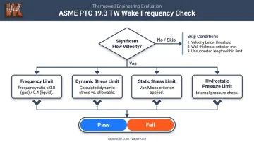
The calculation can be skipped only when all three conditions are met:
- Fluid velocity below 0.64 m/s
- Wall thickness of at least 9.55 mm
- Unsupported length no more than 0.61 m
If a standard thermowell fails the check, options include shortening insertion length, switching to a tapered profile, or specifying a Scruton (helical strake) design.
Frequently Asked Questions
What goes inside a thermowell?
A temperature sensor — most commonly a thermocouple, RTD, or bimetal thermometer probe — inserts into the open end of the thermowell. The sensor tip should contact the closed bore bottom, typically held there by a spring mechanism to ensure accurate heat transfer without air gaps.
What is the difference between an RTD and a thermocouple?
An RTD (Resistance Temperature Detector) measures temperature by detecting changes in the electrical resistance of a platinum element. A thermocouple generates a small voltage via the Seebeck effect at the junction of two dissimilar metals and requires a cold-junction reference for accurate measurement. RTDs are generally more accurate; thermocouples handle wider temperature ranges.
What materials are thermowells typically made from?
316 stainless steel covers most general-service applications: cost-effective and corrosion-resistant. Carbon steel suits low-temperature, non-corrosive conditions only. Inconel, Monel, and Hastelloy are specified where corrosion or extreme temperatures would degrade stainless steel too quickly.
What is the difference between straight, stepped, and tapered thermowells?
Straight thermowells have a uniform OD: strongest and most erosion-resistant, but slowest to respond. Stepped thermowells reduce OD near the tip for faster response while maintaining root stiffness. Tapered thermowells decrease gradually from root to tip, offering the best balance of vibration resistance, strength, and response time, making them the standard choice for demanding applications.
What causes thermowell failure?
The four primary failure modes are vibration-induced fatigue from vortex shedding (most common), corrosion from incompatible process media, erosion from abrasive particles, and improper installation such as incorrect insertion length. The 1995 Monju sodium leak, caused by flow-induced vibration fatigue in a thermocouple well, remains the most cited real-world consequence of unchecked vibration loads.