Introduction
In precision manufacturing, even a deviation of a few thousandths of an inch can mean the difference between a component that performs flawlessly and one that fails catastrophically under load. The Challenger disaster's O-ring failure and the 2024 Boeing door plug incident both trace back to tolerance deviations measured in hundredths of an inch. Dimensional precision isn't just a quality metric: it's a risk management imperative.
Getting that precision right — and keeping it — requires understanding the full picture. This guide covers:
- What numeric thresholds define "tight tolerance" machining
- The four tolerance types engineers commonly specify
- Key factors that determine achievable precision
- Why protecting dimensional accuracy after machining matters as much as achieving it
Key Takeaways
- Tight tolerance CNC machining holds dimensions within ±0.001 inches or better, compared to standard tolerances of ±0.005 inches
- Four tolerance types—dimensional, geometric (GD&T), surface finish, and form—each control different aspects of part quality
- Key factors—material behavior, machine rigidity, toolpath strategy, and inspection protocols—determine whether tight tolerances hold consistently
- Safety-critical industries like aerospace, oil & gas, medical devices, and petrochemicals depend on tight tolerances for reliable component performance
- Surface treatments like diffusion coatings protect tight machined dimensions from wear and corrosion throughout the component's service life
What Is Considered a Tight Tolerance in CNC Machining?
Tolerance is the allowable deviation from a specified dimension, expressed as a plus/minus range (for example, ±0.005 inches). No CNC machine hits an exact measurement every time. Tolerances define the acceptable window within which a part remains functional.
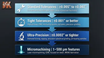
Industry heuristics establish numeric thresholds that distinguish tolerance categories:
- Standard tolerances: ±0.005" to ±0.002" (achievable on conventional CNC mills and lathes)
- Tight tolerances: ±0.001" or better (require deliberate process controls)
- Ultra-precision: ±0.0002" or tighter (used in micromachining and EDM)
- Micromachining: Feature sizes and tolerances from 1 to 500 µm, with femtosecond laser processes achieving sub-micrometer accuracy
Three questions come up frequently when specifying tolerances:
Is ±0.005" considered tight? No. While ±0.005" sits at the upper boundary of standard machining capability, engineers don't classify it as "tight" for demanding applications. Anything tighter starts requiring more rigorous process controls, thermal management, and inspection protocols.
What does "working to tight tolerances" mean in practice? Machinists must account for thermal expansion, tool wear, vibration, and material behavior at every step — through programming, fixturing, tooling, and continuous inspection. It's a system-level discipline, not a single machine setting.
What is the "tightest tolerance"? Advanced processes like femtosecond laser machining can achieve sub-micron precision in controlled environments. In production, however, chasing the tightest possible tolerance without functional justification drives up cost and lead time sharply. Practical tight tolerance work balances dimensional requirements against manufacturing economics.
That gap between what's possible and what's practical becomes especially clear when you look at what tight tolerances actually protect against.
Why Tight Tolerances Matter Beyond Fit
Tight tolerances govern performance outcomes far beyond simple part fit:
- Reduced vibration and friction in rotating assemblies, where misalignment increases vibration response and compromises operational safety
- Prevention of leakage in hydraulic and pneumatic systems operating under high pressure
- Predictable load distribution in structural components, where dimensional deviations alter stress paths
For industries like aerospace, oil drilling, and petrochemical processing, out-of-tolerance components trigger catastrophic failures. The NASA Rogers Commission report on the Challenger disaster highlighted that tolerance deviations in solid rocket motor joints, combined with joint rotation under pressure, caused primary O-ring seal failure. More recently, an NTSB preliminary report (DCA24MA063) on a commercial aircraft door plug blowout noted seal flushness out of tolerance by 0.01 inches. Tight tolerances are a risk management tool, not just a quality specification.
The 4 Types of Tolerance in Machining
Engineers specify four primary tolerance types on engineering drawings, each controlling a different dimensional characteristic:
Dimensional Tolerance
Dimensional tolerance is the allowable variation in a linear measurement—length, width, diameter, or depth—expressed as ±X inches or millimeters. This is the most commonly referenced tolerance type and applies to basic feature sizes.
Geometric Tolerance (GD&T)
Geometric Dimensioning and Tolerancing (GD&T) is a standardized symbolic language governed by ASME Y14.5-2018 (R2024) that controls the shape, orientation, and location of part features. GD&T includes controls like:
- Flatness and straightness (form controls)
- Perpendicularity and parallelism (orientation controls)
- Concentricity and true position
In tight-tolerance assemblies—turbine housings, hydraulic valve bodies, precision gearboxes—dimensional accuracy alone won't guarantee correct fit. GD&T closes that gap by controlling how features relate to each other in three dimensions.
Surface Finish Tolerance
Surface finish tolerance controls the texture of a machined surface, expressed as Ra (roughness average) in microinches or micrometers. ISO 21920-2:2021 supersedes the older ISO 4287 standard, changing the evaluation method so Ra is now calculated over the entire evaluation length. In the US, ASME B46.1-2019 remains the governing standard.
Tighter surface finish requirements directly affect how parts seal, slide, or bond, and typically demand additional finishing passes, grinding, or lapping.
Form Tolerance
Form tolerances control the geometric shape of individual features independent of their size or location. ASME Y14.5-2018 defines four primary form tolerances, none of which require a datum reference:
- Circularity — roundness of a cross-section
- Cylindricity — combined roundness and straightness along an axis
- Flatness — deviation across a planar surface
- Straightness — deviation along a single line element
Form tolerances are critical for bearing bores and sealing surfaces where even microscopic deviation causes leaks, bearing seizure, or assembly failure.
Key Factors That Affect Tight Tolerance CNC Machining
Achieving tight tolerances consistently is a system problem: it requires alignment across material, machine, programming, environment, and inspection. A weakness in any one factor compromises the whole.
Material Properties and Machinability
Material behavior during cutting affects achievable tolerances:
- Aluminum (6061-T6 / 7075-T6): Highly machinable (rated at 50% on the aluminum machinability scale) and holds tight tolerances well, but highly susceptible to thermal expansion
- Stainless Steel (304 / 316): Austenitic grades have high ductility and work harden easily, complicating chip formation; machinability rated at 45% compared to free-cutting steel
- Titanium (Ti-6Al-4V): Exceptionally poor machinability (rated at 25%) due to low thermal conductivity concentrating heat at the cutting edge and low modulus causing springiness
- Engineering Plastics (PEEK / Acetal): Lower thermal conductivity and melting points lead to rapid heat build-up; lower stiffness requires careful support to avoid deflection
Thermal Expansion Impacts
A minor temperature shift can destroy a tight tolerance budget. ISO 1:2016 mandates that all geometrical product specifications are defined at exactly 20 °C (68 °F).
Thermal expansion on a 4-inch (101.6 mm) part with a 10 °C temperature shift:
| Material | Linear CTE (µm/m-°C) | Dimensional Change |
|---|---|---|
| Aluminum 6061-T6 | 23.6 | 0.0009" (23.98 µm) |
| Stainless 304 | 17.3 | 0.0007" (17.58 µm) |
| Titanium Ti-6Al-4V | 8.6 | 0.0003" (8.74 µm) |
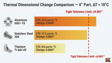
A 10 °C shift on a 4-inch aluminum part consumes nearly 0.001" of tolerance purely through thermal expansion—before any machining errors occur.
Machine Capability and Rigidity
High-precision CNC machining centers with rigid frames, linear encoders, and temperature compensation systems can hold tighter tolerances than standard machines. Advanced CMMs (coordinate measuring machines) achieve Maximum Permissible Errors (MPE) of 0.3 to 0.5 µm.
NIST's "factor of four" rule dictates that a 1 µm part tolerance requires 0.25 µm measurement accuracy. Shops capable of consistent tight tolerance work integrate CMM verification and in-process gauging throughout production.
CNC Programming and Toolpath Strategy
Skilled CNC programmers reduce tolerance error by using optimized toolpaths, controlled feed rates, multiple finish passes, and tool radius compensation. Poor programming choices (aggressive cuts that flex the tool or generate excessive heat) can push a part out of tolerance even on a high-quality machine.
Fixturing and Workholding
Inadequate workholding causes part movement during cutting, introducing dimensional errors. Precision fixturing for tight tolerance work typically involves:
- Custom soft jaws machined to match the part geometry
- Controlled clamping pressure that holds rigidly without distorting thin walls
- Dedicated fixtures engineered for repeatability across production runs
Inspection and Quality Control
Tolerance achievement is only confirmed through measurement. Shops that cannot document and verify dimensions at every stage cannot reliably deliver precision parts at scale. Essential checkpoints include:
- First-article inspection before full production runs begin
- In-process dimensional checks at critical machining stages
- Final CMM verification with documented results
Industries That Rely on Tight Tolerance CNC Machining
Aerospace and Defense
Aerospace parts — engine components, guidance system housings, and structural brackets — must meet tolerances governed by AS9100D standards. Out-of-tolerance parts are scrapped, not reworked.
Cost of Poor Quality (CoPQ) in aerospace reaches 5-30% of gross sales, driven primarily by out-of-tolerance components requiring troubleshooting, scrap, and rework.
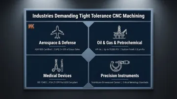
Oil & Gas, Petrochemical, and Industrial Processing
Wellhead components, valve bodies, pump housings, and heat exchanger parts all operate under extreme pressure and temperature — conditions where tolerance failures mean leaks, not just rejects.
API Specification 6A governs wellhead and tree equipment rated up to 20,000 psi, mandating surface finishes of 0.8 µm Ra (32 µin RMS) on BX ring gasket surfaces to maintain sealing integrity.
Medical Devices and Precision Instruments
Surgical tools, implant components, and diagnostic device parts require both dimensional precision and surface finish control to meet FDA 21 CFR Part 820 and ISO 13485:2016 regulatory standards.
Tolerance deviations in implants or surgical instruments can cause device rejection, implant failure, or regulatory recall — consequences that go well beyond a rejected batch.
Managing Cost and Protecting Precision-Machined Parts
The True Cost of Tighter Tolerances
Tighter tolerances increase machining time (more passes, slower feeds), tooling wear, inspection time, and scrap rates. As tolerances tighten, costs rise exponentially due to the need for higher-grade materials, advanced CNC equipment, and enhanced quality control procedures.
The practical engineering guideline: specify tight tolerances only where functionally necessary. Work with machinists early in the design phase, use GD&T to specify tolerance only on critical-to-function features, and consider prototyping to validate tolerance requirements before committing to production runs.
How Surface Treatments Preserve Tight Tolerance Work
Controlling costs during machining is only half the challenge — tight tolerances mean nothing if dimensional accuracy degrades in service. Wear, corrosion, and surface degradation from abrasive or chemically aggressive environments erode precision over time, causing the same fit-and-function failures that tight tolerancing was designed to prevent.
Diffusion coating processes—such as boronizing and aluminizing—provide a proven method to protect precision-machined components. These chemical vapor deposition coatings form an intermetallic compound at the surface that dramatically increases hardness (up to RC75+ equivalency, or 1500–2200 HV) and corrosion resistance.
Key performance characteristics of boronizing on precision components:
- Achieves surface hardness up to RC75+ equivalency (1500–2200 HV)
- Creates case depths of 50 to 400 µm depending on substrate and process
- Dimensional growth is predictable — typically one-fifth to one-third of total boride layer thickness
- Forms a metallurgical bond with the substrate, eliminating the cracking and spallation common with thermal-sprayed overlay coatings
Because dimensional growth is predictable, CNC machinists can pre-compensate during the initial machining phase — ensuring the final treated component stays within its tight tolerance band after coating.
VaporKote has provided boronizing and aluminizing services since 1987, processing components up to 68 inches in diameter for oil drilling, petrochemical, aerospace, and mining applications. All work adheres to ASTM, ASME, SAE, and API engineering codes — relevant when tight tolerances and long-term dimensional stability both need to be documented and verified.
Frequently Asked Questions
What is considered a tight tolerance in machining?
Tight tolerance in CNC machining is generally defined as dimensions held within ±0.001 inches or better, compared to standard tolerances of ±0.005" to ±0.002". What qualifies as "tight" also depends on the application and industry.
Is 0.005 a tight tolerance?
No. ±0.005 inches sits at the boundary of standard machining capability—achievable on conventional CNC equipment but not typically classified as a tight tolerance for precision applications. For demanding industries, tight tolerances begin at ±0.001" and tighter.
What does "tightest tolerance" mean?
The tightest tolerance refers to the smallest dimensional variation a manufacturing process can reliably hold. In advanced micromachining and laser machining, this can reach as small as 1 micron (±0.00004 inches), though practicality and cost impose real limits.
What are the 4 types of tolerance?
The four main types are:
- Dimensional tolerance — variation in linear measurements
- Geometric tolerance — shape and position per GD&T
- Surface finish tolerance — texture/roughness expressed as Ra
- Form tolerance — circularity, flatness, and cylindricity
Most engineering drawings specify a combination of these.
What does working to tight tolerances mean?
Working to tight tolerances means every stage of the machining process is deliberately controlled — from material selection and fixturing through cutting and inspection. The goal is to consistently produce parts within a very narrow acceptable deviation from the design specification.