Introduction
A machinist receives a print calling for ±0.005" tolerances—manageable for any experienced shop. Then the next job arrives: ±0.0005". That single zero redefines the entire process. At ±0.0005", you're working at a scale closer to a white blood cell (6-8 µm) than a human hair (20-180 µm). A few degrees of temperature swing or a tenth of a thousandth of tool runout can push an entire batch out of spec.
Many manufacturers claim they can hold tight tolerances, but real-world results vary widely. Equipment capability, thermal environment, material behavior, workholding strategy, and post-processing decisions all determine whether a shop consistently delivers parts within spec — or scraps entire runs at final inspection.
The six tips below address each of these variables directly, along with the common mistakes that derail even experienced teams.
Key Takeaways
- Tight tolerances (±0.005" and below) demand precise control of equipment, environment, workholding, and tooling—programming alone isn't enough
- Most shops underestimate thermal variation: a 12-inch aluminum part grows 0.000157" per 1°F temperature change
- In-process inspection catches drift early; final-only inspection discovers problems after an entire run is at risk
- Post-processing steps alter dimensions—coatings and heat treatments must be factored into tolerance plans upfront
- Holding tight tolerances consistently means treating it as a full-system discipline, not a single-step fix
What Are Tight Tolerances in Manufacturing?
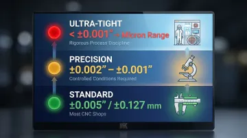
In practical terms, tight tolerance typically refers to any dimensional requirement tighter than ±0.005" (0.127 mm). Precision work pushes to ±0.002" to ±0.001", while ultra-precision drops below ±0.001" into the micron range. What counts as "tight" is relative; standard machining tolerances of ±0.010" are routine in general fabrication but would be unacceptable in aerospace or medical device manufacturing.
Tolerance tiers:
- Standard (±0.005" / ±0.127 mm): achievable by most competent CNC shops
- Precision (±0.002" to ±0.001" / ±0.050 to ±0.025 mm): requires controlled conditions and specialized equipment
- Ultra-tight (below ±0.001" / ±0.025 mm down to a few microns): demands rigorous process discipline and environmental control
Tight tolerances are non-negotiable in aerospace, defense, oil & gas, petrochemical, and medical device manufacturing. In these environments, even a fraction of a thousandth of an inch can trigger component failure, assembly failures, or safety incidents.
Turbine blades and fuel system components rely on dimensional accuracy to seal and cycle correctly. Surgical instruments require it for safe, repeatable performance in the field.
6 Tips for Holding Tight Tolerances in Manufacturing
Tip 1: Invest in Rigid, High-Precision Equipment
Machine rigidity is foundational. Lightweight or worn CNC machines introduce vibration and deflection that make sub-0.001" tolerances nearly impossible to hold consistently. Heavy-duty machining centers with high-speed spindles, rigid cast-iron beds, and advanced look-ahead controls allow the machine to self-adjust feed rates to maintain accuracy on demanding features.
Modern 5-axis machining centers achieve single-digit micron accuracy:
- DMG MORI DMU 80 P duoBLOCK: 4 µm positioning accuracy (standard), 3 µm with µPrecision option, 13 µm volumetric accuracy
- Mazak VC-500A/5X: Submicron control with MX Hybrid Roller Guide System and extremely rigid cast iron base
- Haas UMC-750: 0.0004"/10" linear accuracy (~10 µm), ±15 arc second angular accuracy
Tooling matters as much as the machine itself. Increasing toolholder runout from 0.00008" to 0.0006" slashes carbide tool life by 66% and triples cost-per-hole. Micro-vibrations from poor concentricity unevenly distribute chip loads, causing premature edge failure.
Toolholding systems for tight tolerance work:
- Shrink-fit holders (Haimer): <0.003 mm (0.00012") TIR, 360° gripping, excellent rigidity
- Hydraulic holders (Kennametal HydroForce): ≤3 µm TIR, superior vibration dampening
- Mechanical precision collets (REGO-FIX powRgrip): ≤3 µm TIR, consistent repeatability
Standard ER collets cannot reliably hold the <3 µm TIR required for ultra-precision finishing. Hydraulic and shrink-fit systems are mandatory.
Tip 2: Control the Thermal Environment
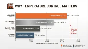
Metal expands and contracts with temperature—even a few degrees of ambient or workpiece temperature change can shift a part out of tolerance for sub-0.001" work. A 12-inch 6061-T6 aluminum component will grow 0.000157" (~4 µm) for every 1°F change in ambient temperature. This single factor can consume an entire ultra-precision tolerance band from minor shop floor temperature swings alone.
Material thermal expansion rates:
| Material | CTE (µin/in-°F) | Expansion for 12" part at +5°F |
|---|---|---|
| Aluminum 6061-T6 | 13.1 | 0.000786" (19.9 µm) |
| 304 Stainless Steel | 9.6 | 0.000576" (14.6 µm) |
| Carbon Steel (AISI 1018) | 6.39 | 0.000383" (9.7 µm) |
| Titanium (Ti-6Al-4V) | 4.78 | 0.000287" (7.3 µm) |
ISO 1:2022 fixes the standard reference temperature for geometrical and dimensional properties at 20°C (68°F). ASME B89.6.2 dictates that metrology laboratories maintain 20°C ± 2°C, with variations less than ±0.5°C per hour.
Practical thermal controls:
- Maintain temperature-stabilized machining environments (ideally 68°F/20°C)
- Allow raw material to thermally stabilize before machining (minimum 2-4 hours for large parts)
- Use coolant consistently—not intermittently—to avoid thermal cycling at the cutting zone
- Consider thermal compensation systems built into modern CNC controls
Tip 3: Master Workholding and Fixturing
A part that shifts, vibrates, or flexes during machining cannot hold tight tolerances regardless of machine precision. Workholding strategy must be engineered for the specific part geometry, material, and operation—not just grabbed from the rack.
Workholding options and tradeoffs:
- Precision vises: Good for rectangular parts, limited accessibility, can distort thin-walled components
- Custom fixtures: Optimized for specific geometry, expensive upfront, excellent repeatability
- Vacuum tables: Uniform clamping force, ideal for thin-walled or delicate parts, requires flat surfaces
- Collet-based systems: Excellent for round parts, high repeatability, limited to specific geometries
Minimizing the number of setups dramatically reduces cumulative error. Transitioning from multi-setup fixturing to single-setup 5-axis machining improves geometric accuracy by up to 33.98%. Every time a part is unclamped and re-clamped, microscopic debris and datum shifts introduce stacking positional errors.
Zero-point clamping systems:
- Schunk VERO-S NSE3: <0.005 mm repeat accuracy
- Hainbuch MANDO Adapt: 0.003 mm repeatability without manual adjustment
- Advanced vacuum systems: ±5 µm initial alignment, 0.5 µm repeatability
Tip 4: Optimize Cutting Parameters and Tool Path Strategy
Aggressive material removal rates may be efficient, but they introduce cutting forces that deflect both the tool and the workpiece. For tight tolerance work, reduce depth of cut and feed rates for finishing passes, and separate roughing and finishing operations so the part can relax and thermal effects can settle before final cuts.
Understanding tool deflection:
Standard cantilever beam formulas underestimate tool deflection by 8.2% to 30.9% because they ignore torsional moments. When the cutting edge is offset from the tool's axis of symmetry, cutting forces induce both bending and twisting, compounding actual deflection well beyond what bending alone predicts.
Trochoidal milling for tight tolerances:
Limiting radial engagement to 5-10% via trochoidal toolpaths reduces peak cutting forces by 40-60%. This prevents heat buildup and drastically lowers the radial forces that push the tool off its programmed path, enabling older machines to cut hard alloys to tight tolerances.
Climb vs. conventional milling:
| Strategy | Chip Formation | Impact on Accuracy |
|---|---|---|
| Climb Milling | Max thickness to zero | Superior surface finish, reduces tool wear, requires zero-backlash machine |
| Conventional Milling | Zero to max thickness | Rougher finish due to initial rubbing, safer for older machines with backlash |
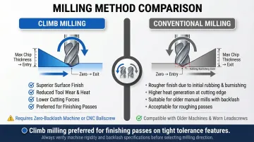
Climb milling is preferred for finishing passes to achieve tight tolerances, provided the machine has backlash compensation and rigid workholding.
CAM software considerations:
Use tolerance-aware tool path options that optimize entry/exit strategies, maintain consistent chip loads, and minimize direction changes that affect surface consistency and dimensional accuracy.
Tip 5: Implement In-Process Inspection—Not Just Final Inspection
Inspecting only finished parts means discovering problems after they've compounded across an entire run. In-process gauging—checking critical dimensions at defined intervals during production—allows operators to catch drift early and make micro-adjustments before scrapping parts.
The 10:1 rule and guardbanding:
The measurement device must have resolution and accuracy significantly better than the tolerance being held. Historically, MIL-STD-120 established the "10:1 rule" stating that measuring equipment accuracy should not exceed 10% of the part tolerance. Relying on simple acceptance without guardbanding can result in up to a 50% Probability of False Acceptance (PFA) at the tolerance limit. Shrinking the acceptance zone by applying a guardband multiplier limits PFA to <2%.
In-process metrology tools:
- Bore gauges (Mitutoyo Series 511): 5 µm accuracy, 2 µm repeatability
- CMM (Hexagon Leitz Infinity): E0 = 0.3 + L/1000 µm (ultra-precision)
- Shop-floor gauge (Renishaw Equator 500): ±0.002 mm comparison uncertainty
- CNC probing systems: Integrated measurement without removing part from machine
Tip 6: Account for Post-Processing and Surface Treatments in Your Tolerance Plan
In-process inspection catches drift during cutting — but even perfectly machined parts can fail final inspection if post-processing is ignored. Heat treatment, plating, coating, and finishing all alter final dimensions, sometimes by amounts that exceed the entire tolerance band. The dimensional change each treatment introduces must be engineered into pre-treatment dimensions from the start.
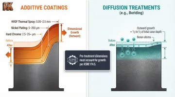
Additive coatings build up on the surface:
- Hard chromium (ASTM B650): Class 1 specifies 2.5 to 25 µm thickness; Class 2 specifies >25 µm
- Nickel electroplating (ASTM B689): Classes dictate minimum thickness from Class 5 (5 µm) up to Class 200 (200 µm)
- Thermal spray (HVOF): Typical coating thicknesses range from 0.05 mm to 2.5 mm (0.002" to 0.100")
Diffusion treatments behave differently:
Unlike additive coatings, diffusion-based treatments form an intermetallic compound within the substrate rather than depositing material on top. The dimensional effect is smaller — but not zero, and it must still be planned for.
Boriding (boronizing) is a thermochemical diffusion process that forms hard metal-boride layers into the substrate at 700–1000°C. Because boron atoms diffuse into the lattice, the part physically grows outward. Studies show this outward growth is typically one-fifth to one-third of the total boride layer depth — so a 150 µm case depth produces 30 to 50 µm of outward growth per side.
VaporKote's chemical vapor deposition process produces a predictable dimensional offset that engineers can calculate and machine to before treatment. Because the growth is consistent and documented, VaporKote provides metallurgical analysis and certification to ASTM, ASME, SAE, and API standards — giving engineering teams a defensible number for pre-treatment drawings.
ASME Y14.5 explicitly requires drawings to state whether dimensions apply "BEFORE PLATING" or "AFTER PLATING." Engineers must calculate pre-treatment offsets based on whether the process is additive or diffusion-based.
Key Variables That Affect Tolerance Achievement
Beyond the six tips, certain inherent variables must be understood and managed:
Part Geometry Complexity
- Thin walls flex under cutting forces and clamping pressure
- Long bores are difficult to measure and prone to deflection
- Deep cavities restrict tool access and coolant flow
- Large parts are more susceptible to thermal growth and machine positional errors
Material Machinability
Aluminum 6061-T6 has a machinability rating of 50%, machining cleanly at tight tolerances with predictable behavior. Ti-6Al-4V is rated at just 17% due to low thermal conductivity and high flexibility, requiring more process care and specialized tooling.
Tooling Wear
A cutter that's acceptable for rough work may introduce enough runout or edge degradation to push tight-tolerance finishing out of spec. Typical normal flank wear for the usable life of a finishing edge ranges from 0.005" to 0.010" (0.127 to 0.254 mm). Allowing wear beyond this increases passive cutting forces, pushing the tool away from the workpiece and causing dimensional drift. Set change intervals based on material and cut count — not just visual inspection.
Operator Consistency and Process Documentation
Even with the best equipment, inconsistent setups, undocumented offsets, or ad-hoc parameter changes between operators or shifts introduce variation. Standardized work instructions and locked offset documentation give you a reproducible baseline — so the next operator starts from the same position the last one finished.
Common Mistakes When Trying to Hold Tight Tolerances
Most tight tolerance failures trace back to the same handful of process gaps. Recognizing these early saves significant rework time and material cost.
Rushing the pre-machining setup. A quick fixture and tool load is rarely enough. Without verifying machine calibration, tool runout, fixture seating, and material stabilization first, first-article failures are almost guaranteed.
Carrying rough-cut parameters into finishing passes. Feed rates, depths of cut, and tool paths that work for roughing will produce out-of-spec parts on finish cuts. Finishing operations for tight tolerance features need their own optimized parameters — reduced speeds, lighter cuts, and climb milling strategies.
Ignoring the downstream tolerance stack-up. Designing to the nominal machined dimension without accounting for heat treatment growth, coating thickness, or surface finishing stock removal leaves no tolerance margin after post-processing. The result is scrap at final inspection — the worst possible point to discover a miss.
Conclusion
Holding tight tolerances in manufacturing is a system-level discipline. It demands alignment across equipment selection, environmental control, workholding, cutting strategy, inspection, and post-processing planning. Any single weak link in the chain can push an otherwise well-machined part out of spec.
Manufacturers who consistently hold tight tolerances treat these six tips as standard operating procedure, not occasional checklists. Investing in process discipline upfront — temperature-controlled environments, zero-point workholding, in-process inspection, and post-processing planning — prevents costly rework, scrap, and delivery failures downstream.
That discipline extends to post-processing as well. Surface treatments like thermal diffusion coatings add measurable material to a part's surface, so pre-coat dimensions must account for that growth to hit final print tolerances. The difference between ±0.005" and ±0.0005" isn't just a decimal place — it's a complete rethinking of how every step in the process gets controlled.
Frequently Asked Questions
What does 'tight tolerance' mean?
Tight tolerance refers to a narrow allowable range of dimensional variation in a manufactured part—typically any tolerance tighter than ±0.005" (0.127 mm). This means the finished part must fall very close to its nominal specified dimension to function correctly in its intended application.
Is 0.005 in. a tight tolerance?
±0.005" is generally considered the boundary between standard and tight tolerances in CNC machining. Most competent shops can achieve this, but anything tighter (±0.002" and below) requires more controlled equipment, environments, and rigorous process discipline.
What is the tolerance for a tight fit?
A "tight fit" in engineering (per ISO and ANSI standards) refers to a shaft-to-hole interference fit, where the shaft is intentionally larger than the hole and requires force for assembly. Specific values depend on fit class and nominal size, but interference fits typically range from 0.0002" to 0.003" depending on the application.
How does a smaller tolerance affect the precision of a machined part?
Tighter tolerances mean less dimensional variation is acceptable, which improves fit, function, and interchangeability. The trade-off is increased manufacturing complexity, cost, and inspection requirements.
What are tight tolerance parts?
Tight tolerance parts are machined or manufactured components where allowable dimensional variation is very small (often ±0.001" or less). These parts are typically required in industries like aerospace, defense, medical devices, and oil & gas where dimensional accuracy is critical to performance and safety.
What are the 4 types of tolerance?
The four common types are dimensional tolerance (size limits), geometric tolerance (form, orientation, location), surface finish tolerance (roughness), and material condition tolerances (MMC/LMC in GD&T). In precision manufacturing, geometric tolerances under GD&T are the most frequently applied.