Introduction
Tubular heat exchangers dominate industrial thermal management, holding a 37% revenue share of the global heat exchanger market ($6.7 billion in 2024, projected to reach $9.2 billion by 2030). These workhorses of oil refining, petrochemical processing, and power generation handle conditions that would destroy plate exchangers.
Extreme pressures, aggressive corrosive fluids, and temperature swings exceeding 800°C are routine operating realities—not edge cases.
Yet selecting the right configuration, managing flow efficiency, and keeping tubes reliable long-term remain persistent challenges. Fouling alone costs U.S. industries an estimated $14 billion annually. Tube failures can shut down a refinery for $500,000 to $1 million per day in lost production.
This guide explains what tubular heat exchangers are, how they work, which type fits your application, and how advanced surface protection extends tube life well beyond untreated materials.
TLDR
- Tubular heat exchangers transfer heat between fluids—one inside tubes, the other flowing around them in a shell
- Shell-and-tube dominates industrial installations, but double-pipe and corrugated variants serve high-pressure and hygienic applications
- They handle extreme pressures (up to 15,000 psi), temperatures (800°C+), and corrosive fluids better than alternatives
- Tube material and surface protection are critical for longevity
- Diffusion coatings like boronizing and aluminizing extend service life 2x to 10x in harsh environments
What Is a Tubular Heat Exchanger?
A tubular heat exchanger transfers thermal energy between two fluids using a bundle of tubes enclosed within a cylindrical shell. The term "tubular heat exchanger" is a broad category covering several distinct designs, with shell-and-tube being the most widely recognized subtype.
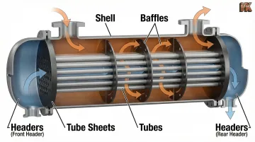
Basic anatomy includes:
- Tubes carry one fluid stream — typically the higher-pressure or more corrosive one
- Tube sheets are thick end plates that hold tubes in place and seal tube-side from shell-side
- Shell: the cylindrical vessel enclosing the tube bundle and carrying the second fluid
- Baffles direct shell-side flow across the tubes and provide structural support
- Headers (front and rear) distribute and collect tube-side fluid at each end
Heat passes between the streams across the tube walls — the two fluids never mix. That efficiency has made tubular designs the dominant technology across petrochemical, energy, and food processing sectors, with the shell-and-tube segment alone accounting for 37% of global heat exchanger revenue.
How Does a Tubular Heat Exchanger Work?
One fluid — typically the hotter "primary" fluid — flows inside the tubes. The second fluid flows through the shell around the outside of those tubes. Heat transfers from the hot fluid to the cooler fluid across the tube walls by conduction and convection.
How efficiently that transfer happens depends on three controllable variables: flow configuration, internal geometry, and design parameters.
Flow Configurations and Thermal Efficiency
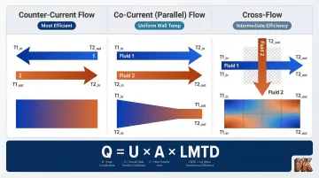
Three flow patterns affect thermal performance:
Counter-current flow (most efficient):
- Fluids flow parallel but in opposite directions
- Maintains consistent temperature gradient throughout the exchanger length
- Allows the largest temperature change in both fluids
- Delivers maximum heat transfer for a given surface area
Co-current (parallel) flow:
- Both fluids enter and exit at the same end
- Temperature difference narrows along the exchanger's length
- Less efficient than counter-current but provides more uniform wall temperatures
- Useful when thermal stress must be minimized
Cross-flow:
- Fluids flow perpendicular to each other
- Commonly used in condensers and air-cooled applications
- Offers intermediate efficiency between counter-current and co-current designs
The Role of Baffles
Baffles on the shell side force fluid to flow across the tubes in a serpentine path rather than straight through. This increases turbulence and improves the heat transfer coefficient while physically supporting the tubes to reduce vibration damage. Baffle spacing directly affects both heat transfer rate and pressure drop—closer spacing boosts performance but increases pumping costs.
Tube Passes and the Performance Tradeoff
More tube passes increase the tube-side fluid velocity and heat transfer rate but also raise pressure drop. Engineers must balance this tradeoff during design: a single-pass exchanger minimizes pressure drop but may not achieve the required heat transfer; a four-pass design maximizes thermal performance but demands more pumping power.
Thermal Design Fundamentals
These design decisions all feed into the same governing equation: Q = U × A × LMTD. Each variable represents a lever engineers can adjust:
- Overall Heat Transfer Coefficient (U): Combines conductive and convective resistance between fluids, plus fouling resistance — higher U means more efficient transfer per unit area
- Log Mean Temperature Difference (LMTD): The logarithmic average of temperature differences at each end of the exchanger, representing the driving force for heat transfer
- Heat Transfer Area (A): Total surface area available for exchange — larger area compensates when U is low or LMTD is narrow
In multipass arrangements, designers apply a correction factor (F) to the LMTD to account for the departure from true counter-current flow. Getting this factor right is what separates an exchanger that meets spec from one that underperforms in the field.
Types of Tubular Heat Exchangers
"Tubular heat exchanger" is an umbrella term covering several distinct designs, each suited to different operating conditions and fluid characteristics.
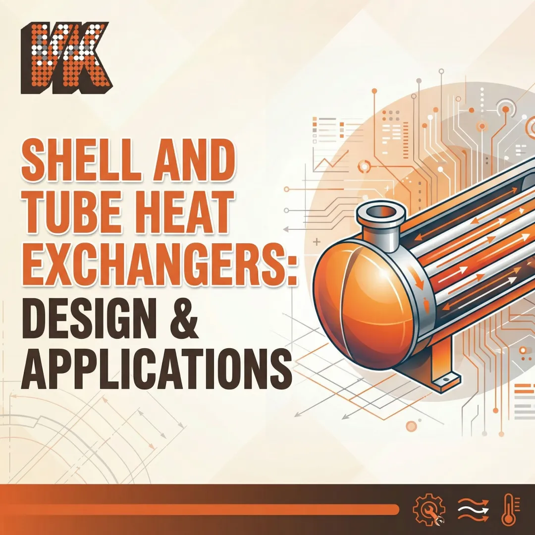
Shell-and-Tube Heat Exchangers
The most common industrial configuration consists of a bundle of straight or U-bent tubes housed inside a cylindrical shell. Three main tube bundle arrangements dominate:
Fixed Tubesheet (TEMA Types L, M, N):
- Simplest and cheapest design per square foot
- Tube bores can be cleaned mechanically or chemically
- Shell side accessible only to chemical cleaning, not mechanical
- Cannot accommodate thermal expansion without shell expansion joints
- Best for clean shell-side fluids and moderate temperature differentials
U-Tube (TEMA Type U):
- Each tube bends in a U-shape, allowing unlimited thermal expansion
- Bundle can be removed for shell-side cleaning
- Tube interiors are difficult to clean mechanically due to U-bends
- Least costly design for removable bundles
- Ideal when shell-side fouling is the primary concern
Floating Head (TEMA Types P, S, T, W):
The most mechanically complex option, floating head designs allow the rear tubesheet to move freely — accommodating unlimited thermal expansion with straight tubes that permit mechanical cleaning on both sides.
- Rear tubesheet is allowed to move/float, accommodating unlimited thermal expansion
- Bundle fully removable for inspection and cleaning
- Straight tubes allow mechanical cleaning of tube interiors
- Typically 25% more expensive than fixed tubesheet due to complex internal seals; mandatory for high-fouling, high-temperature differential applications

Double-Pipe (Hairpin) Heat Exchangers
A double-pipe exchanger consists of one tube inside another, with one fluid flowing through the inner tube and the other in the annular space between the two. This is the simplest tubular design, best suited for small heat duties (under 300 square feet), high-pressure applications, or situations where true counter-current flow is needed.
Key advantages:
- Can handle extreme tube-side pressures up to 15,000 psi and shell-side pressures up to 2,400 psi
- Operates in true counter-current flow without LMTD correction penalties
- Hairpin or U-bend configurations extend capacity for larger duties
- Small shell diameters make them more cost-effective for high-pressure service
Corrugated Tube and Multi-Tube Variants
Beyond single-tube configurations, corrugated and multi-tube designs address specialized fluid handling challenges. Corrugated tube exchangers feature alternating grooves and ridges that induce turbulent flow, disrupting the thermal boundary layer and improving heat transfer efficiency by 123% to 232% compared to smooth tubes — at a 1.46x to 1.93x friction/pressure drop penalty.
Double-tube, triple-tube, and multi-tube variants are built for viscous or particulate-laden fluids. Key characteristics include:
- Widely used in food processing, dairy, and pharmaceutical industries
- Comply with 3-A Sanitary Standard 12-08 for product integrity
- Enhanced turbulence reduces fouling accumulation
- Compatible with cleaning-in-place (CIP) protocols
Advantages and Disadvantages of Tubular Heat Exchangers
Advantages
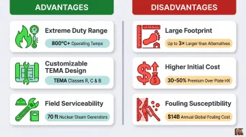
Tubular heat exchangers excel across the full spectrum of industrial demands:
- Extreme duty range: Handles pressures and temperatures from cryogenic LNG service to 800°C+ oxidizing environments, accommodating gas-to-gas, liquid-to-liquid, two-phase, and corrosive fluid combinations that would damage plate exchangers
- Customizable design: TEMA standardization allows tube lengths, diameters, baffle types, and materials to be tailored to a specific duty—at Tabriz Petrochemical, swapping a segmental bundle for a helical equivalent cut maintenance costs by 60% and tripled operational run times
- Field serviceability: U-tube and floating-head configurations allow the tube bundle to be pulled for inspection, mechanical cleaning, or replacement—critical where refinery shutdowns cost $500,000 to $1 million per day
Disadvantages
The tradeoffs are equally significant:
- Large footprint: Units can span several tens of meters; nuclear U-tube steam generators reach 70 feet (21 meters) in height, weigh up to 800 tons, and house up to 16,000 tubes—demanding real estate that compact plate exchangers don't require
- Higher initial cost: Floating-head designs run roughly 25% more than fixed tubesheet units due to complex internal seals and machining tolerances; high-alloy materials like titanium or duplex stainless push upfront costs further
- Fouling susceptibility: Mineral deposits, biofilm, and process residues degrade heat transfer coefficients and raise pressure drop over time; fouling in U.S. industrial heat exchangers costs an estimated $14 billion annually and wastes 2.9 Quads of energy—and fixed tubesheet designs limit shell-side cleaning access
Industries and Applications
Tubular heat exchangers are used across virtually every major industrial sector:
Petrochemical and Oil Refining:
- Crude oil preheating
- Distillation column condensers and reboilers
- Product coolers
- Hydrogen compression and LNG liquefaction
Power Generation:
- Feedwater heaters
- Steam condensers
- Nuclear steam generators
Chemical Processing:
- Reactor feed/effluent exchangers
- Solvent recovery
- Process cooling and heating
Food and Beverage:
- Pasteurization
- Product cooling
- Heat recovery in dairy processing
Pharmaceutical/Biotech:
- Sterile processing
- Solvent heating
- Temperature-controlled fermentation
The specific type selected—shell-and-tube, double-pipe, or corrugated tube—depends on fluid characteristics (viscosity, particulate content, cleanliness requirement), operating pressure and temperature, and applicable regulatory requirements.
Key governing standards include:
- ASME BPVC Section VIII — pressure vessel design and fabrication
- API Standard 660 — petroleum and petrochemical applications
- 3-A Sanitary Standard 12-08 — sanitary design for food and pharmaceutical processing
In oil refining, petrochemical, and mining operations, tubular heat exchangers routinely handle aggressive, corrosive, or abrasive fluids at elevated temperatures. These conditions accelerate tube wall degradation, making material selection and surface protection critical to service life.
Materials, Maintenance, and Protective Coatings
Common Tube Materials
| Material | Selection Drivers & Limitations |
|---|---|
| Carbon Steel | Non-corrosive fluids at moderate temperatures. Strong and affordable, but highly susceptible to corrosion without protection. |
| 316L / Duplex Stainless | Excellent for petrochemical services and corrosive environments. Duplex (e.g., 2205) combines high strength with superior chloride resistance. |
| Titanium (Grade 2) | Outstanding resistance to pitting, crevice corrosion, and biofouling. Lifecycle-cost winner for highly aggressive chloride service and warm seawater, despite high initial cost. |
| Copper-Nickel (90/10, 70/30) | Excels in natural seawater and marine environments due to good heat transfer and biofouling resistance. Must avoid trace sulfides/H₂S or ammonia, which trigger rapid attack. |
| Monel, Incoloy | Specialty alloys for extreme chemical resistance or high-temperature strength. |
Degradation Mechanisms
Even with correct material selection, tube surfaces in harsh industrial environments are vulnerable to:
- Erosion-corrosion — Solid particles in moving fluids strip away passive layers, accelerating wall loss beyond what chemical attack alone would cause
- Pitting corrosion — Localized cavities that are difficult to detect or predict, often causing rapid, unexpected perforation; petroleum refining preheat trains typically see failures every three to four years from pitting or sulfidation
- High-temperature oxidation — In environments above 1,200°F, reactive gases and fluxing agents chemically attack tube metal, shortening equipment life
These degradation mechanisms reduce wall thickness, create hot spots, and ultimately lead to tube failure, leaks, and unplanned shutdowns costing refineries $500,000 to $1 million per day in lost production.
Addressing these failure modes before they escalate is where surface engineering makes a measurable difference.
Diffusion Coating Technologies
Diffusion coating technologies—such as boronizing and aluminizing—create an intermetallic compound at the tube surface that increases hardness and corrosion resistance far beyond what the base metal alone can achieve.
Boronizing (Boriding):
- Diffuses boron into metal surfaces at 700°C to 1000°C to form hard, wear-resistant metal-boride layers
- Achieves surface hardness of 1400–2000 HV (RC75+ equivalency)—harder than tungsten carbide cutting tools
- Extends tube life 2x to 10x in erosive environments
- Ideal for components subject to abrasive slurries or high-velocity particulate flows
Aluminizing (Calorizing):
- Chemical vapor deposition process (governed by ASTM B875) where aluminum diffuses into the substrate at high temperatures
- Forms stable intermetallic compounds providing exceptional oxidation and sulfidation resistance
- Protects steels and alloys exposed to aggressive gaseous environments at elevated temperatures up to 800°C–950°C
- Cost-effective method for extending heat exchanger tube service life
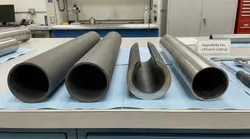
VaporKote has applied boronizing and aluminizing processes to industrial components since 1987, adhering to ASTM, ASME, SAE, and API engineering codes. Because the coating diffuses into the substrate rather than sitting on top of it, the bond is metallurgical—not mechanical. This eliminates the spalling, peeling, and delamination failures that thermal spray and paint coatings are prone to under thermal cycling and pressure fluctuations, making diffusion-coated tubing a more reliable long-term choice for severe-service heat exchangers.
Frequently Asked Questions
Which is better: tubular heat exchangers or shell-and-tube heat exchangers?
Shell-and-tube is actually a subtype of tubular heat exchanger. "Tubular" is the broader category. Comparing them is like comparing a vehicle to a car; shell-and-tube is simply the most common and widely used tubular design.
What is a tubular heat exchanger?
A tubular heat exchanger transfers heat between two fluids using a bundle of tubes enclosed within a shell. One fluid flows inside the tubes and the other flows around them. They account for a dominant 37% revenue share of the global heat exchanger market.
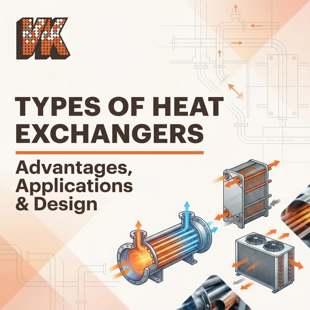
What are the four main types of heat exchangers?
The four broad categories are shell-and-tube (tubular), plate heat exchangers, air-cooled (fin-fan) heat exchangers, and double-pipe heat exchangers. Shell-and-tube dominates high-pressure and corrosive applications, while plate exchangers suit compact, low-fouling duties. Air-cooled units eliminate water consumption; double-pipe designs excel at extreme pressures.
What is the 2/3 rule for heat exchangers?
The 2/3 rule is a guideline suggesting that baffle spacing and baffle cut should be proportioned so crossflow and window velocities are approximately equal, balancing heat transfer efficiency against pressure drop. It's a starting estimate, not a final design standard. TEMA strictly specifies minimum baffle spacing at 20% of shell inside diameter or 2 inches, whichever is greater.
What industries use tubular heat exchangers?
Primary industries include oil and gas, petrochemical and refining, power generation, chemical processing, food and beverage, pharmaceutical, and mining. Their ability to handle extreme pressures, temperatures, and aggressive fluids makes them the dominant choice for heavy industry.
How do you maintain a tubular heat exchanger?
A standard maintenance program typically covers:
- Mechanical cleaning via tube-side rodding or hydroblasting
- Chemical cleaning to remove scale and deposits
- Regular inspection for wall thinning or corrosion
- Protective diffusion coatings (boronizing or aluminizing) to slow corrosion and extend intervals between shutdowns