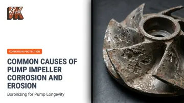
Introduction
Pump impellers are at the heart of nearly every industrial fluid-handling system, and the punishment they absorb is relentless. In mining, petrochemical processing, and oil production, impellers face a relentless combination of abrasive solids, reactive chemicals, and hydraulic forces that progressively destroy their geometry and efficiency.
The cost of ignoring this damage is steep. A 2024 downtime study reported by Pumps & Systems found that unplanned incidents cost offshore operations an average of $38 million per year, with mining operations losing $180,000 per downtime event. A significant share of those incidents traces back to impeller degradation that was either misdiagnosed or ignored too long.
This article breaks down the four primary causes of pump impeller corrosion and erosion, explains the damage patterns each leaves behind, and covers practical prevention strategies: material selection, protective coatings, and operating discipline.
Key Takeaways
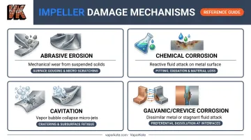
- Four mechanisms drive impeller damage — abrasive erosion, chemical corrosion, cavitation, and galvanic/crevice corrosion — each with a distinct failure pattern
- Each mechanism leaves distinct visual signatures that aid root-cause diagnosis
- Unchecked damage reduces hydraulic efficiency, increases power draw, and accelerates failure across surrounding components
- Effective prevention relies on material compatibility, protective coatings, proper NPSH management, and fluid quality control
- Early warning signs — noise, pressure drop, vibration — allow intervention before total failure
Common Causes of Pump Impeller Corrosion and Erosion
Before diagnosing a damaged impeller, it helps to understand what you're actually looking at. Erosion is mechanical material removal (abrasive particles or hydraulic forces physically strip away metal). Corrosion is chemical degradation: reactive constituents in the fluid attack and break down the metal surface.
These two mechanisms rarely operate in isolation. Corrosion weakens surface layers, making them easier to erode. Erosion strips away the passive oxide films that protect against corrosion — together, they accelerate damage far faster than either would alone.
Impeller damage typically arises from one or more of the following four root causes, each producing recognizable patterns.
Abrasive Erosion from Suspended Particles
Solids suspended in the pumped fluid (sand, silt, ore slurry, grit) physically wear down vane surfaces through repeated high-velocity impact. Damage concentrates where flow velocity peaks: the leading edges of vanes, high-flow passages, and discharge zones. Furrowing (parallel grooves running along the vane surface in the direction of flow) is the characteristic visual indicator.
Key amplifiers of erosion rate:
- Particle hardness — harder particles (quartz, silica) cut more aggressively than softer ones
- Particle size and concentration — larger particles at higher concentrations accelerate wear non-linearly; wear rate scales with velocity to approximately the 2.4th power according to Xylem's material guidance for wastewater pumps
- Flow velocity — even modest increases in impeller speed dramatically increase erosion
Industries most exposed include mining slurry transfer, dredging, grit-laden wastewater, and sand-laden oil production. A 2023 slurry pump study published in Water Science reported impeller wall erosion at 0.09 g/m²·s at 1% slurry (nine times the erosion rate measured at the volute wall) along with a 22.47% average head reduction.
Chemical Corrosion from Fluid Composition
Chemical corrosion occurs when the pumped fluid reacts with the impeller metal. Unlike erosion's localized, velocity-driven wear, corrosion tends to produce more evenly distributed surface damage across all exposed surfaces, including shroud exteriors — a useful distinction when diagnosing damage type.
Common triggering conditions:
- Acid or caustic process fluids in chemical plants
- Seawater or brine in marine and desalination applications
- Chlorinated water in treatment facilities (chlorine concentrations as low as 2 ppm can trigger dezincification in bronze alloys)
Dezincification deserves specific mention for bronze impellers. In silicon bronze or brass alloys containing 16% or more zinc, chlorine exposure causes zinc to leach out of the alloy, leaving behind a weakened, porous copper matrix with a distinctive reddish discoloration.
The damage can closely mimic cavitation pitting in appearance, making correct diagnosis critical. Temperature compounds the problem: a 10°C rise roughly doubles corrosion rate in many systems.
Cavitation-Induced Erosion
Cavitation forms when localized pressure at the impeller inlet drops below the fluid's vapor pressure, creating vapor bubbles. When those bubbles move into higher-pressure zones, they implode violently, releasing micro-jets of energy that pit and erode the impeller surface.
Two distinct patterns identify the type:
- Suction cavitation — pitting near the leading edge of vanes, caused by insufficient Net Positive Suction Head (NPSH)
- Low-flow recirculation — damage near the impeller eye from operating too far left of Best Efficiency Point (BEP), generating internal flow recirculation, noise, and vibration
Per Pumps & Systems, NPSH available must exceed NPSH required for operation without cavitation or head loss — and operating far right of BEP can exhaust available NPSH entirely. API 610 defines preferred operating range as 70% to 120% of BEP flow, with rated flow ideally between 80% and 110%.
Beyond direct pitting, cavitation strips away protective surface oxide layers, leaving bare metal exposed to accelerated corrosion — even in fluids that wouldn't normally cause corrosion damage.
Galvanic and Crevice Corrosion
Galvanic corrosion occurs when two dissimilar metals contact each other in the presence of a conductive (electrolytic) fluid. The less noble metal becomes the anode and corrodes preferentially. TAMU seawater pump guidance identifies a potential difference of 0.25 V as the threshold for galvanic couple risk in seawater.
In practice, a graphitically corroded cast iron casing (common in older pumps) can generate enough galvanic current to rapidly destroy a newly installed bronze impeller.
Crevice corrosion is a related but distinct mechanism. It develops in confined spaces around flanges, fasteners, and tight clearance gaps where fluid becomes stagnant. Oxygen depletes inside the crevice, pH drops, and localized attack accelerates. This is particularly problematic in pumps that operate intermittently, where trapped fluid sits for extended periods.
Two conditions drive the highest crevice corrosion risk:
- Intermittent pump operation — stagnant fluid sits in confined gaps between cycles, accelerating oxygen depletion
- **Chloride exposure on stainless steel** — stainless impellers rely on a passive oxide film for protection; in stagnant, oxygen-depleted conditions, chloride ions break that film down, triggering localized pitting
Understanding these four failure mechanisms helps pinpoint not just what failed, but why — and which surface treatments or material upgrades will provide the most durable protection going forward.
What Happens When Impeller Damage Goes Unchecked
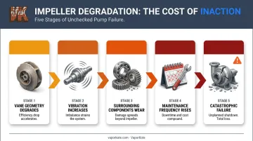
Impeller degradation rarely announces itself with a sudden breakdown. Performance erodes in stages, each one compounding the next:
- Vane geometry degrades — hydraulic efficiency drops, requiring more power to maintain flow
- Vibration increases — uneven material loss across vanes creates imbalance; bearing loads rise
- Surrounding components wear faster — seals, bearings, and casing experience accelerated degradation driven by imbalance and turbulence
- Maintenance frequency increases — more frequent interventions compound operating costs
- Catastrophic failure — unplanned shutdown requiring full pump replacement
Published research puts hard numbers on this progression. One double-suction pump study found 3.0 to 4.5 mm erosion pits near trailing edges after just 10,000 hours of sediment service. A separate Engineering Failure Analysis case study documented impellers losing approximately 20% of their mass from cavitation erosion, with failures occurring between 1,900 and 3,000 hours.
Warning Signs to Monitor
These symptoms warrant immediate investigation, not a "monitor and wait" response:
- Grinding, crackling, or gravel-like noise — indicates cavitation or abrasive particle presence in the flow stream
- Unexplained drop in flow rate or discharge pressure — points to geometric degradation of vanes without any change in operating conditions
- Rising vibration levels or bearing temperatures — signals impeller imbalance from uneven material loss
Vibration monitoring can detect developing pump problems up to 18 months before breakdown, according to Wilcoxon Sensing Technologies — providing a substantial window for planned intervention rather than emergency repair.
How to Prevent Pump Impeller Corrosion and Erosion
Effective prevention combines material and coating decisions made before installation with operating discipline maintained throughout service life.
Select Impeller Materials Compatible with the Pumped Fluid
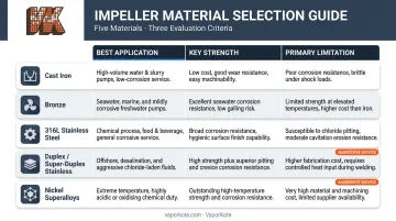
Material selection should follow a thorough analysis of fluid chemistry (pH, chloride content, oxidizing agents), operating temperature, and solid content. A general guide:
| Material | Best For | Limitations |
|---|---|---|
| Cast iron | Neutral-pH, low-abrasion service | Poor acid and chloride resistance |
| Bronze | Saltwater and brine resistance | Soft against abrasives; dezincification risk with >16% zinc |
| 316L stainless steel | Broad chemical resistance (Mo content) | Vulnerable to crevice corrosion in stagnant chloride environments |
| Duplex / super-duplex stainless | Seawater service (PREN ≥40 required) | Higher cost; requires careful welding and fabrication |
| Nickel superalloys | Highly aggressive acid and high-temp media | Significant cost premium |
Verify that all wetted components — not just the impeller — are metallurgically compatible. Mixing bronze impellers in stainless housings, or cast iron combined with copper alloys in conductive fluids, introduces galvanic couples that undermine even well-chosen impeller material.
Apply Advanced Protective Surface Coatings
Protective coatings create a barrier between the base metal and the operating environment, extending service life without full component replacement. Options span a wide range:
- Fusion-bonded epoxy — suitable for moderate corrosion in lower-velocity applications
- Tungsten carbide thermal spray (WC-Co-Cr) — addresses abrasion in slurry environments; a 2019 Wear journal study found that adding 3% Mo₂C to WC-Co-Cr coatings improved slurry erosion performance by 69.6%
- Diffusion coatings (boronizing) — go beyond surface-layer application by forming an intermetallic compound at the base metal surface through chemical vapor deposition, creating a metallurgical bond rather than a mechanical one
VaporKote's boronizing process, applied with all impeller surfaces protected, achieves a surface hardness of 1500 Knoop (RC75+ equivalency) — harder than tungsten carbide cutting tools. Because the coating diffuses metallurgically into the substrate, it cannot delaminate under cyclic hydraulic loading the way thermal spray or epoxy coatings can.
VaporKote also performs metallurgical analysis and certifies diffusion coatings on processed parts, with capacity to handle components up to 68 inches in diameter. For impellers already showing erosion damage, integrated machining and repair services can restore geometry before coating application.
For impellers facing simultaneous abrasive erosion and chemical attack — acid mine drainage or chloride-laden slurry, for example — diffusion coating's combined hardness and corrosion resistance is the strongest available defense.
Optimize Operating Conditions to Eliminate Cavitation
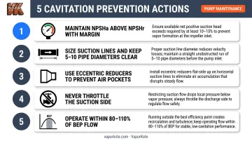
Cavitation is preventable. The actions that eliminate it:
- Ensure NPSHa consistently exceeds NPSHr with appropriate margin — ANSI/HI 9.6.1 specifies that required margin depends on pump energy level, suction specific speed, and fluid characteristics
- Size suction lines properly and keep them free of blockages; maintain 5 to 10 pipe diameters of straight run between pump inlet and upstream obstructions
- Use eccentric reducers on suction lines to prevent air pockets
- Avoid throttling the suction side
- Operate within 80% to 110% of BEP flow (API 610 preferred operating range)
Operating significantly off-BEP creates internal recirculation and turbulence that drives both cavitation damage and accelerated vane erosion — even in clean, chemically neutral fluids.
Manage Fluid Quality Through Filtration and Treatment
Upstream fluid management reduces the erosive and corrosive load reaching the impeller:
- Install properly sized suction strainers to remove abrasive solids (note that clogged strainers reduce NPSHa and can themselves trigger cavitation)
- Control pH and dissolved oxygen in process water through chemical treatment
- Apply corrosion inhibitors where appropriate — for marine systems, ferrous chloride dosing can form a protective surface layer
- Review fluid treatment protocols whenever process composition changes: seasonal water quality variation, feedstock changes, or introduction of new chemical streams
Tips for Long-Term Impeller Protection
Sustaining impeller protection over a pump's full service life requires ongoing discipline:
- Establish routine inspection schedules combining visual examination (look for pitting, furrowing, uneven wear) with performance trend monitoring across flow, pressure, and power consumption
- Maintain detailed maintenance logs for each pump unit, recording fluid chemistry, coating condition, and operational anomalies to support proactive re-coating decisions
- Train maintenance personnel to distinguish between erosion damage (localized furrowing), corrosion damage (distributed surface attack), and cavitation pitting (concentrated near vane edges), so root causes get resolved rather than just components replaced
- Deploy vibration sensors and flow meters for continuous health monitoring, enabling predictive maintenance that avoids unplanned shutdowns
Conclusion
Pump impeller corrosion and erosion aren't random failures — they're predictable consequences of specific operating conditions, fluid chemistry, and material choices. The damage patterns each mechanism leaves behind are readable, provided maintenance teams know what to look for.
Combining compatible material selection, metallurgically bonded protective coatings, hydraulic discipline around NPSH and BEP, and active fluid management can dramatically extend impeller service life and reduce total cost of ownership.
For operations in mining, petrochemical, or oil production environments where multiple damage mechanisms act simultaneously, diffusion coating technology — such as boronizing, which achieves surface hardness exceeding RC75 — provides protection that integrates into the substrate itself rather than sitting on top of it. That structural depth is what separates it from surface-level treatments when conditions get severe.
Frequently Asked Questions
What is the life expectancy of an impeller?
Impeller lifespan varies widely — from under a year in aggressive slurry or highly corrosive service to over a decade in clean, well-controlled applications. The primary factors are fluid chemistry, solid content, operating conditions, and whether protective coatings are applied.
What causes pump impeller damage?
The four main causes are abrasive erosion from suspended particles, chemical corrosion from reactive fluid constituents, cavitation from localized pressure drops, and galvanic or crevice corrosion from metal incompatibilities or stagnant fluid zones. These mechanisms frequently occur together and accelerate each other.
How much does it cost to replace an impeller?
Replacement parts range from a few hundred dollars for small pumps to over $10,000 for large industrial impellers. Beyond the part itself, unplanned downtime and production losses (in some industries exceeding $180,000 per incident) typically dwarf the part cost — making preventive coatings and condition monitoring the lower-cost option over any meaningful service horizon.
What is the difference between erosion and corrosion in pump impellers?
Erosion is mechanical: abrasive particles or cavitation forces physically remove material, concentrated where velocity is highest. Corrosion is chemical: reactive fluid constituents degrade the metal surface more evenly across all exposed areas. Both frequently occur simultaneously, each accelerating the other.
Can cavitation damage an impeller even if the fluid is not chemically corrosive?
Yes. Cavitation causes purely mechanical erosion through micro-jet impacts from collapsing vapor bubbles. Clean, chemically neutral water can cause severe impeller pitting if cavitation conditions persist.
What surface coatings offer the best protection against impeller corrosion and erosion?
The best choice depends on the dominant damage mechanism. Polymeric coatings suit moderate corrosion in lower-velocity service; tungsten carbide thermal spray addresses abrasion in slurry environments. For combined abrasive and chemical attack, diffusion coatings such as boronizing deliver 1500 Knoop hardness (RC75+ equivalency) with a metallurgical bond that resists both mechanisms at once.