Introduction
Pump wear rings rank among the most overlooked components in centrifugal pumps, yet they wield enormous influence over efficiency, reliability, and operating costs. A worn wear ring just a few thousandths of an inch beyond specification can cost thousands of dollars annually through lost efficiency, accelerated component damage, and unplanned downtime.
This guide covers wear ring function, clearance specifications, material selection, and surface treatments that extend service life — with references to API 610, the governing standard for petrochemical, oil and gas, and industrial pump applications.
TLDR:
- Wear rings restrict internal fluid bypass between impeller and casing, protecting efficiency and reducing cavitation risk
- API 610 sets minimum diametral clearances starting at 0.010" for rings ≤2" OD, scaling upward with diameter
- Replace rings when clearance reaches approximately twice original specification to prevent severe efficiency loss
- Material pairing must avoid galling: minimum 50 BHN hardness differential unless both surfaces exceed 400 BHN
- Diffusion coatings like boronizing achieve RC75+ hardness, extending service intervals in demanding applications
What Are Pump Wear Rings and What Do They Do?
A pump wear ring is a replaceable, precision-machined component that creates a controlled clearance gap between the rotating impeller and stationary pump casing to limit internal fluid recirculation.
The Hydraulic Problem Wear Rings Solve
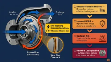
As the impeller spins and pressurizes fluid, a pressure differential drives some fluid to leak back from the high-pressure discharge side around the impeller periphery toward the low-pressure suction eye. Wear rings act as a throttling device to restrict this internal bypass flow, which would otherwise:
- Reduce volumetric efficiency
- Increase the pump's Net Positive Suction Head Required (NPSHR)
- Generate turbulence at the impeller eye that triggers or worsens cavitation
- Cause erosion of the impeller and casing
These effects compound over time. Research shows that reducing wear ring clearance by 50% using non-galling composite materials yields a 2-4% efficiency gain and lowers NPSHR by up to 10 feet.
Mechanical Function: Axial Thrust Balancing
Beyond controlling recirculation, wear rings serve a second distinct role: balancing axial thrust forces on the impeller. Rear wear rings work in tandem with balancing holes to reduce suction pressure behind the impeller. This limits axial thrust force, reduces bearing loads, and improves rotor stability — extending the service life of bearings and mechanical seals.
Sacrificial Design Philosophy
Wear rings are intentionally manufactured as sacrificial components — made from materials that cost far less to replace than the impeller or casing they protect. When clearances open up from wear, you replace the rings, not the pump's most expensive castings. That's the practical engineering logic behind their design.
Where Are Wear Rings Located in a Centrifugal Pump and How Many Are There?
Wear rings can be mounted in two positions:
- On the impeller skirt (rotating wear ring / impeller wear ring)
- In the pump casing (stationary wear ring / casing wear ring)
Standard Configuration
A typical single-stage centrifugal pump includes both a casing ring and an impeller ring working together as a matched pair. Pumps with closed-style impellers generally include both a casing wear ring and an impeller wear ring fitted to the outside diameter of the impeller suction eye. These impellers may also feature rear wear rings to control axial thrust.
Some pump designs use only a casing ring against an integral impeller wear surface, or only an impeller ring against an integral casing surface. Multi-stage pumps will have wear ring pairs at each stage.
When Pumps Omit Wear Rings
Not all pumps include wear rings. Very small pumps, some slurry pumps, and pumps designed for abrasive fluids may omit them if:
- The recirculation losses are acceptable
- The solids content would rapidly destroy the rings
- Tight clearances would cause clogging with foreign matter
When a pump is installed in a wastewater or slurry application, enlarged wear ring clearances or complete omission prevents foreign matter such as grit, rags, and wipes from becoming tangled between the impeller and casing. In these cases, accepting lower hydraulic efficiency is a deliberate design choice — not a flaw — to keep the pump running reliably in harsh conditions.
Understanding Wear Ring Clearances: The Critical Balancing Act
What Is Diametral Clearance?
"Diametral clearance" is the total gap measured across the diameter (not the radius) between the OD of the rotating ring and the ID of the stationary ring. This is the primary specification that governs both efficiency and safety.
Two Failure Modes of Incorrect Clearance
Clearance errors fall into two failure modes:
- Too tight: Metal-to-metal contact between rotating and stationary rings generates heat, vibration, and potentially catastrophic seizure.
- Too loose: Excessive internal recirculation reduces head, increases power consumption, and accelerates erosion. Experimental studies showed that enlarging clearance from 0.25 mm to 0.85 mm varied flow rate by -6% to +5%, head by -10% to +6%, and efficiency by -19% to +2%.
API 610 Minimum Diametral Clearances
| Impeller Wear Ring OD | API 610 Minimum Diametral Clearance |
|---|---|
| < 2.000" (< 50 mm) | 0.010" (0.25 mm) |
| 2.000" to 2.499" (50 to 64.99 mm) | 0.011" (0.28 mm) |
| 5.000" to 5.999" (125 to 149.99 mm) | 0.017" (0.43 mm) |
| 10.000" to 10.999" (250 to 274.99 mm) | 0.022" (0.55 mm) |
The minimum grows with ring diameter to accommodate thermal expansion and shaft deflection. API 610 mandates that 0.005" (125 µm) must be added to standard diametral clearances for materials with higher galling tendencies or for all materials operating at temperatures above 500°F (260°C).
Measuring Wear Ring Clearance in the Field
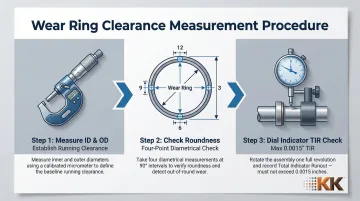
Knowing the spec is one thing — confirming it in the field is another. Follow these steps:
- Measure the ID of the stationary part and the OD of the rotating part with a micrometer to establish running clearance.
- Check for roundness by taking diametrical readings at four points 90° apart (12, 3, 6, and 9 o'clock positions).
- Before final assembly, mount a dial indicator on the impeller wear ring OD and rotate the shaft. TIR must not exceed 0.0015" (0.04 mm).
The "2x" Replacement Rule
The standard industry rule of thumb is to replace wear rings when measured diametral clearance reaches approximately twice the original new clearance. While often attributed to API standards, API 610 does not explicitly mandate replacement at this threshold; rather, it requires that thrust bearings be sized for continuous operation at twice the design internal clearances.
The "2x rule" serves as a practical maintenance trigger to prevent severe efficiency loss and vibration before bearing failure occurs.
Wear Ring Material Selection: Matching the Ring to the Application
The Foundational Principle: Avoiding Galling
The stationary and rotating ring surfaces must not be a galling combination. Similar-metal contact under load causes adhesive wear and seizing. API 610 requires a minimum 50 Brinell Hardness Number (BHN) differential between mating metallic rings to prevent galling, unless both surfaces exceed 400 BHN.
Common Metal Wear Ring Materials
- Cast iron: common in water service and an economical baseline
- Bronze: good corrosion resistance and natural anti-galling properties for general industrial use
- Stainless steel: suited for corrosive services, though austenitic grades have high galling tendencies requiring the 0.005" clearance adder
- Hardened stainless or chrome steels: higher wear resistance for abrasive environments
Material must be compatible with the pumped fluid to avoid galvanic corrosion or chemical attack.
Non-Metallic and Composite Wear Rings
Materials like PEEK, carbon graphite, and fiber-reinforced composites are non-galling and allow reduced running clearances (sometimes by up to 50%) because seizure risk is eliminated. API 610 Table H.3 explicitly approves nonmetallic wear part materials, including PEEK and resin-impregnated carbon graphite.
Reducing wear ring clearance with non-metallic materials increases rotor damping and stiffness—a phenomenon known as the Lomakin Effect. This added stiffness reduces vibration and shaft deflection, extending mechanical seal life. Nonmetallic materials also eliminate metal-to-metal interfaces within the pump, drastically reducing the risk of catastrophic pump seizure during off-design events.
When evaluating non-metallic options, account for thermal expansion, fluid compatibility, and distortion under pressure — all of which vary significantly between PEEK, carbon graphite, and composite grades.
Advanced Surface Hardening: Boronizing
Diffusion coating processes such as boronizing can significantly increase the surface hardness of metallic wear rings. VaporKote's boronizing services create an intermetallic compound at the surface rather than depositing a layer on top, meaning the coating cannot flake or delaminate.
Boronized pump wear rings from VaporKote deliver measurable performance advantages:
- 1500 Knoop (RC75+ equivalent) surface hardness — harder than tungsten carbide cutting tools
- ~20x less wear loss than unprotected steels in ASTM G65 dry sand abrasion testing
- Tighter operating clearances and longer service intervals compared to standard metallic rings
The dense boride layer provides excellent corrosion resistance in harsh oil refining, petrochemical, and marine pump applications. VaporKote's processes adhere to ASTM, ASME, SAE, and API engineering codes — a requirement for refinery, offshore, and mining pump specifications.
To find out whether boronizing is the right fit for your wear ring application, contact VaporKote for an application review.
Signs of Wear Ring Failure and When to Replace Them
Operational Symptoms
Worn wear rings manifest through hydraulic and mechanical symptoms:
- Reduced pump head and flow output for the same power input
- Higher power consumption to maintain system demands
- Elevated casing temperature from increased internal recirculation
- Increased vibration and noise as rotor stability degrades
- More frequent cavitation events due to elevated NPSHR
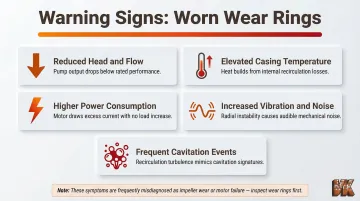
These symptoms develop gradually and are frequently misdiagnosed as impeller or motor problems.
Inspection Process
Check wear rings during scheduled pump teardowns by measuring actual clearance and comparing to OEM specs and API 610 limits. Once disassembled, visual inspection can reveal:
- Scoring or galling marks
- Uneven wear patterns indicating misalignment
- Pitting or material transfer on the ring surface
Replacement Timing Guidance
When inspection findings point to excessive wear, replacement timing becomes critical. Most manufacturers and API 610 recommend replacement when measured diametral clearance reaches approximately twice the original (new) clearance. Beyond that threshold, widened clearances destroy the Lomakin effect — the hydrodynamic stiffness that stabilizes the rotor — exposing the pump to additional radial loading, shaft deflection, and eventual mechanical seal face separation. Tracking clearance measurements at each teardown is the most reliable way to stay ahead of this failure mode.
Extending Wear Ring Life: The Role of Surface Coatings
Replacing wear rings on a standard cycle is the default approach, but advanced surface treatments can extend service intervals significantly and reduce total lifecycle cost — making surface treatment a reliability engineering decision, not just a maintenance one.
How Diffusion Coatings Differ from Conventional Methods
Diffusion coatings like boronizing penetrate the base metal to form an intermetallic compound at the surface rather than depositing a layer on top. This means the coating cannot flake or delaminate, providing a structurally superior alternative than conventional plating or thermal spray.
VaporKote's boronized pump wear rings achieve 1500 Knoop (RC75+ equivalent) surface hardness and have consistently outperformed other surface treatments in demanding industrial applications. Case studies show that 17-4PH stainless steel fluid pump components treated with boronizing saw their wear rate drop from 16.4 × 10^-5 mm³/Nm to 3.3 × 10^-5 mm³/Nm—a fivefold improvement.
Corrosion Resistance Advantages
Coated wear rings also deliver corrosion resistance that matters in the most demanding pump environments. The dense boride layer protects components exposed to:
- H2S and CO2 in oil refining and production
- Chloride-laden fluids in marine and petrochemical service
- Aggressive process chemicals in pulp, paper, and chemical processing
VaporKote's processes adhere to ASTM, ASME, SAE, and API engineering codes, ensuring compliance with industry standards. With over 37 years of diffusion coating experience and on-site powder formulation capabilities, VaporKote's engineering team can evaluate your specific wear ring application and recommend the most effective treatment path.
Frequently Asked Questions
What is a pump wear ring and what does it do?
A wear ring is a replaceable component mounted at the impeller-casing interface that controls internal recirculation by maintaining a precise clearance gap. It protects pump efficiency and the more expensive impeller and casing from erosion while helping balance axial thrust forces.
Where are the wear rings located on a centrifugal pump?
Wear rings can be fitted on the impeller skirt (rotating ring), in the pump casing (stationary ring), or in both positions as a matched pair. The dual-ring configuration—one rotating, one stationary—is the most common arrangement in industrial centrifugal pumps.
How many wear rings are in a centrifugal pump?
A single-stage centrifugal pump typically has one or two wear rings (casing and/or impeller), while multi-stage pumps have a ring set at each stage.
How does wear on a pump wear ring affect centrifugal pump performance?
As clearance grows with wear, more fluid bypasses the impeller internally—reducing head, flow, and volumetric efficiency while increasing power draw, heat, vibration, and cavitation risk. Left unaddressed, this accelerates erosion of surrounding components and shortens pump service life.
How do you measure wear ring clearance in a centrifugal pump?
During disassembly, use a dial indicator or feeler gauges to measure diametral clearance at multiple circumferential points (90° apart). Compare readings against OEM specs or API 610 minimums to confirm whether replacement is needed.
Do all pumps have wear rings?
Most centrifugal pumps include wear rings. However, some designs—such as very small pumps, slurry pumps, or those handling abrasive fluids—may omit them when wear rates would be too high or the performance trade-off is acceptable.